Novel composite type compensator for pipeline

A composite and compensator technology, which is applied to the structure of thermal pipeline compensation device and the field of thermal pipeline compensation device, can solve the problems of weak anti-corrosion link, large gap, leakage and so on.

Inactive Publication Date: 2012-09-05
陈墅庚
View PDF7 Cites 2 Cited by
  • Summary
  • Abstract
  • Description
  • Claims
  • Application Information

AI Technical Summary

Problems solved by technology

Among them: the cost of the spherical compensator is too high, while the performance of the domestically produced spherical compensator is average, and the pressure loss is large; the corrugated compensator has too much stress in the pipeline in practical application, and there are always hidden safety hazards in the pipeline operation; and the original П-shaped compensator is used The investment and pressure loss of the natural compensation method are the same; the structure and sealing performance of the sleeve type compensator are not good, the leakage phenomenon is serious, and the anti-corrosion link is also weak; the performance of the rotary compensator is better; it has a large amount of compensation, Flexible layout, especially in long-distance overhead pipelines, has obvious advantages; but there are also shortcomings: First, the gap between the joint part of the inner pipe and the reducing pipe is too large, and eddy currents will be generated at this part during the movement of the fluid medium. This increases the pressure loss of the fluid medium
Second, because the structure of the rotary compensator is a radial working principle, it must occupy a certain space when it is applied in the pipeline; and each set of compensator installation points must be equipped with a drain valve; this increases the cost and pressure loss of the pipeline network; Especially in buried pipelines, it cannot be widely used; especially spherical compensators, sleeve compensators, corrugated compensators, and rotary compensators all adopt a single sealing form. In terms of use: fluid medium and pressure bearing capacity, etc. subject to certain limitations

Method used


Image

  • Novel composite type compensator for pipeline
  • Novel composite type compensator for pipeline
  • Novel composite type compensator for pipeline

Examples


Embodiment Construction

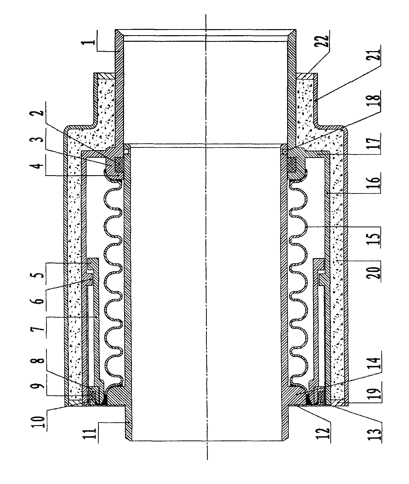
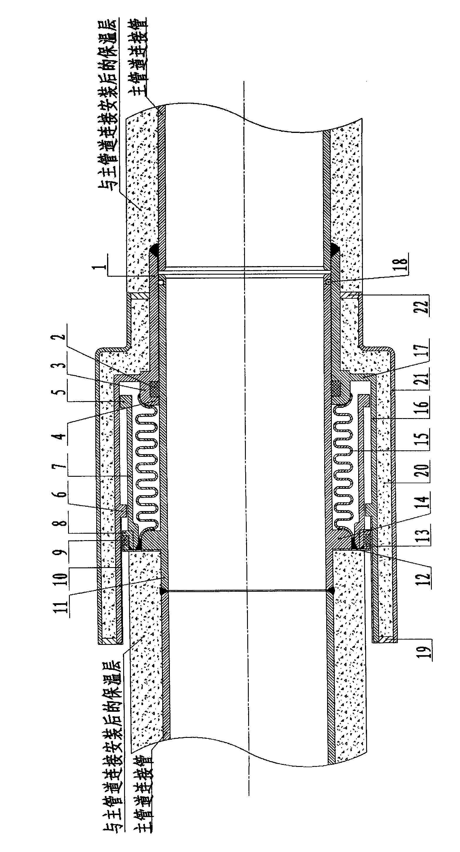
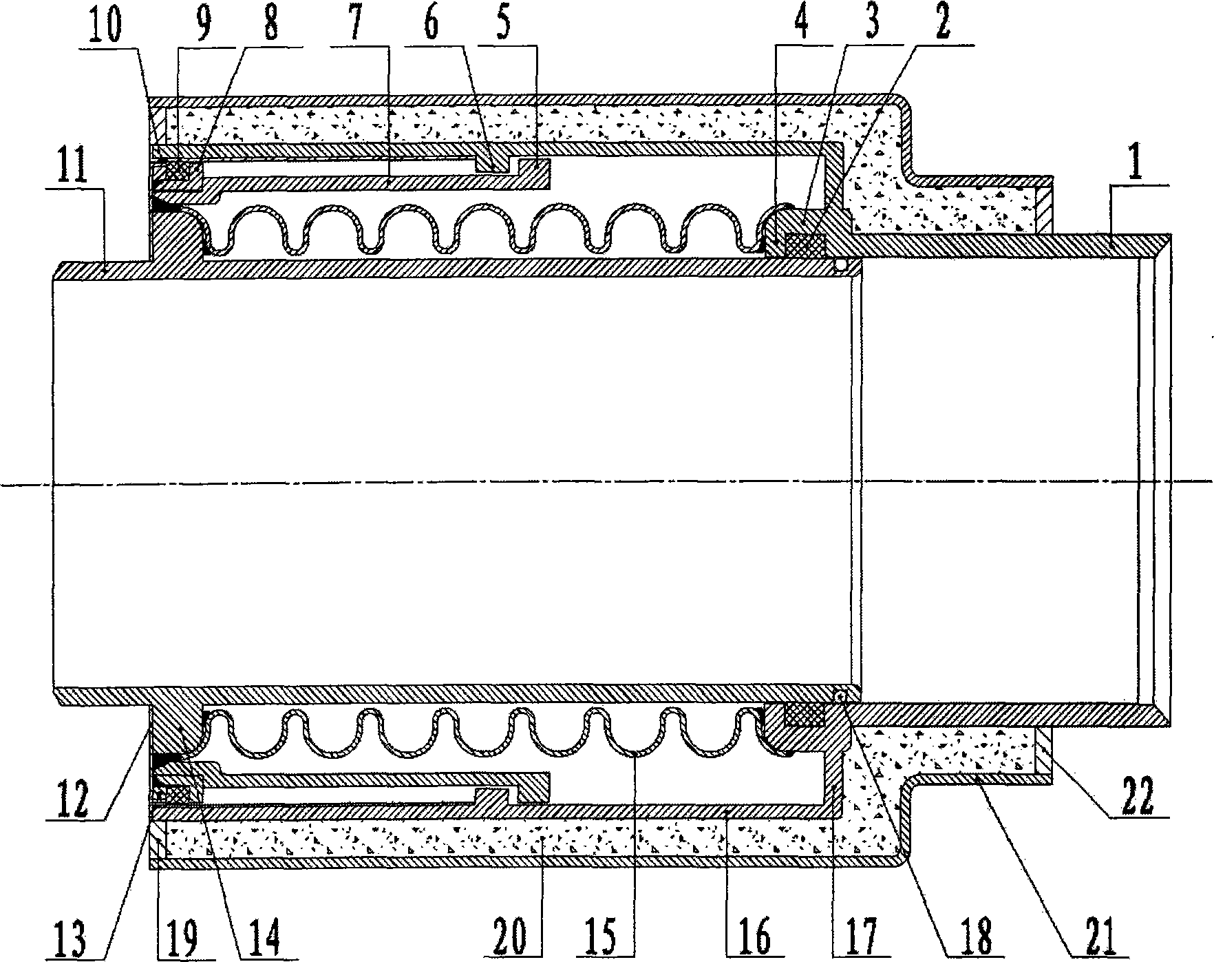
[0052] Below with the accompanying drawings figure 1 (Schematic diagram of the structure before absorption heat displacement) and figure 2 (Schematic diagram of the structure after absorbing thermal displacement) The technical solution of the present invention is described in detail as follows.

[0053] like figure 1 A schematic diagram of the structure before absorbing heat displacement, a new composite compensator for pipelines, including outer connecting sleeve 1, seal A2, outer connecting sleeve convex outer ring 3, seal A head 4, plunger inner tube Convex outer ring 5, anti-pull-off limit ring 6, plunger inner tube 7, annular sealing structure 8, seal B9, anti-corrosion layer A10, core tube 11, anti-corrosion layer B12, seal B head 13, core tube convex Outer ring 14, bellows 15, plunger outer pipe 16, plunger outer pipe structure 17, steel ball 18, anti-corrosion jacket structure A19, heat insulating filler 20 anti-corrosion jacket 21 and anti-corrosion jacket structur...


PUM


Abstract

The invention discloses a novel composite type compensator for a pipeline, belonging to the technical field of a compensation device for a thermal pipeline. According to the novel composite type compensator for the pipeline provided by the invention, a convex outer ring for a core pipe is arranged on the core pipe; an outer connection casing pipe is coaxially and annularly sleeved on an outer ring at one end of the core pipe; a corrugated pipe is annularly sleeved on the surface of the outer ring of the core pipe, and the both ends of the corrugated pipe are respectively fastened and fixedly connected with the convex outer ring for the core pipe and a sealing head of a sealing piece A; a plunger inner pipe is sleeved at the outer side of the corrugated pipe; a plunger outer pipe is sleeved at the outer side of the plunger inner pipe, so as to form a structure that the core pipe consisting of the plunger inner pipe integrally connected with the outer ring, an annular sealing framework, a sealing piece B and the corrugated pipe can entirely coaxially and synchronously move along an axial direction when being pushed and squeezed through an axial heat expansion force. With the adoption of the structure, the novel composite type compensator has the advantages of reducing a pipeline stress, enhancing a sealing property, improving bearing capability, having anti-corrosion effect, and realizing large compensation amount.

Description

technical field [0001] The invention relates to a novel composite compensator for pipelines, which belongs to the technical field of thermal pipeline compensation devices, and specifically belongs to the technical field of thermal pipeline compensation device structures used in industries such as petroleum, chemical industry, light industry, thermal power, and metallurgy. Background technique [0002] Common pipeline compensation methods in the prior art are as follows: 1. Traditional natural U-bend type, 2. Spherical compensator, 3. Sleeve compensator, 4. Corrugated compensator, 5. Rotary compensator. Among them: the cost of the spherical compensator is too high, and the performance of the domestically produced spherical compensator is average, and the pressure loss is large; the corrugated compensator has too much stress in the pipeline in practical application, and there are always hidden safety hazards in the pipeline operation; and the original П-shaped compensator is us...

Claims


Application Information

Patent Timeline
IPC IPC(8): F16L51/02F16L58/18F16L59/18
Inventor 陈墅庚陈振兴陈达远高轶徐峰于幸
Owner 陈墅庚
Why Eureka
Try Eureka