Plunger type multifunctional pipeline compensator

A pipeline compensator and multi-functional technology, which is applied in the field of thermal pipeline compensator and thermal pipeline compensator structure, can solve the problems of occupation, increase of pipeline network cost and pressure loss, poor structure and sealing performance of sleeve type compensator, etc.

Active Publication Date: 2012-06-27
陈墅庚
View PDF8 Cites 2 Cited by
  • Summary
  • Abstract
  • Description
  • Claims
  • Application Information

AI Technical Summary

Problems solved by technology

Among them: the cost of the spherical compensator is too high, and the performance of the domestically produced spherical compensator is average, and the pressure loss is relatively large; the corrugated compensator has too much stress in the pipeline in actual application, and there is always a safety hazard in the pipeline operation; and the original II-shaped compensator is used The investment and pressure loss of the natural compensation method are the same; the structure and sealing performance of the sleeve compensator are not good, the leakage phenomenon is serious, and the anti-corrosion link is also weak; the performance of the rotary compensator is better; it has a large amount of compensation, Flexible layout, especially in long-distance overhead pipelines, has obvious advantages; but there are also shortcomings: First, the gap between the joint part of the inner pipe and the reducing pipe is too large, and eddy currents will be generated at this part during the movement of the fluid medium. This increases the pressure loss of the fluid medium
Second, because the structure of the rotary compensator is a radial working principle, it must occupy a certain amount of extra space when it is applied in the pipeline; and each set of compensator installation points must be equipped with a steam trap; this increases the cost and pressure of the pipeline network. damage; and it cannot be widely used in buried pipelines; especially spherical compensators, sleeve compensators, corrugated compensators, and rotary compensators all adopt a single sealing form. In use: fluid medium and bearing Pressure capacity and other aspects are subject to certain limitations

Method used


Image

  • Plunger type multifunctional pipeline compensator
  • Plunger type multifunctional pipeline compensator
  • Plunger type multifunctional pipeline compensator

Examples


Embodiment Construction

[0057] The technical solutions of the present invention are described in detail below in conjunction with the accompanying drawings.

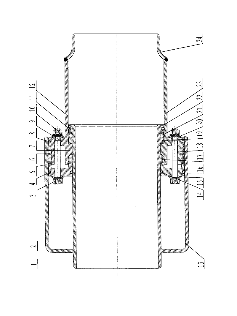
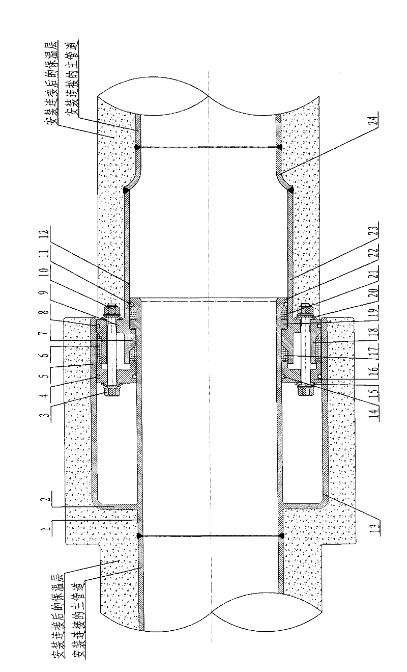
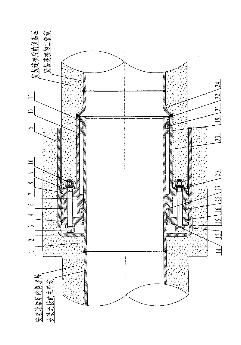
[0058] Such as figure 1 As shown, a plunger-type multi-functional pipeline compensator includes a core tube 1, a plunger outer tube structure 2, a bolt 3, a steel ball C4, a plunger outer tube 5, a seal C6, an outer sleeve inner bearing platform 7, and a steel ball D8 , plunger inner tube structure 9, nut 10, steel ball A11, anti-corrosion bushing A12, anti-corrosion bushing B13, steel ball B14, floating pretensioner A15, sealing gland flange 16, seal B17, plunger inner tube 18. Core tube protruding outer ring 19, floating pretensioner B20, seal A21, seal A head 22, outer sleeve 23 and variable diameter adapter 24;

[0059] The core tube 1 is a straight tube structure, and the inner end protrudes along the outer ring in turn to be provided with a core tube convex outer ring 19 and a sealing member A head 22; A plunger outer tube structure 2 w...


PUM


Abstract

The invention discloses a plunger type multifunctional pipeline compensator, which belongs to the technical field of heat distribution pipeline compensation devices. A fixed sealing press cover flange and a reducing connection pipe are adopted. An outer sleeve assembly with an outer sleeve inner bearing platform, a plunger inner pipe framework and a plunger inner pipe is integrally sleeved at one end of a core pipe assembly with a plunger outer pipe framework, a plunger outer pipe, a core pipe convex outer ring and a sealing part A. A steel ball and a sealing part are used for straightening. When one end is extruded and pushed by axial thermal expansion force, the core pipe assembly and the outer sleeve assembly can synchronously, integrally and relatively move in coaxial mode. By means of the structure, stress of pipelines is reduced, sealing performance is enhanced, bearing capacity is improved, the effect of corrosion resistance is provided, and the purpose of large compensation amount and wide application scope can be achieved.

Description

technical field [0001] The invention relates to a plunger-type multifunctional pipeline compensator, which belongs to the technical field of thermal pipeline compensation devices, and specifically belongs to the technical field of thermal pipeline compensation device structures used in industries such as petroleum, chemical industry, light industry, thermal power, and metallurgy. Background technique [0002] Common pipeline compensation methods in the prior art are as follows: 1. Traditional natural U-bend type, 2. Spherical compensator, 3. Sleeve compensator, 4. Corrugated compensator, 5. Rotary compensator. Among them: the cost of the spherical compensator is too high, and the performance of the domestically produced spherical compensator is average, and the pressure loss is relatively large; the corrugated compensator has too much stress in the pipeline in actual application, and there is always a safety hazard in the pipeline operation; and the original II-shaped compens...

Claims


Application Information

Patent Timeline
Patent Type & Authority Applications(China)
IPC IPC(8): F16L51/00F16L59/21
Inventor 陈墅庚于幸徐峰陈振兴高轶陈达远
Owner 陈墅庚
Why Eureka
Try Eureka