
Centrifugal-temperature composite test box

A composite test and test chamber technology, which is applied in the testing/calibration of speed/acceleration/shock measurement equipment, speed/acceleration/shock measurement, and measuring devices, etc. It can solve the problem that the accuracy of the temperature environment cannot meet the calibration requirements and cannot achieve centrifugation Machine and other problems, to achieve the effect of solving the uneven temperature of the gas, facilitating experimental installation and transportation, and high heating and cooling efficiency

Inactive Publication Date: 2014-05-07
BEIHANG UNIV
View PDF4 Cites 13 Cited by
  • Summary
  • Abstract
  • Description
  • Claims
  • Application Information

AI Technical Summary

Problems solved by technology

[0003] At present, for the test chamber that can generally work on the centrifuge, it is often unable to withstand high centrifugal acceleration. The installation of the test chamber and the installation of the accelerometer are mutually restricted, and due to factors such as uneven gas under centrifugal conditions, the accuracy of the temperature environment provided is generally up to The low temperature calibration environment under the rotating working state of the centrifuge is often not possible if the calibration requirements are not met

Method used


Image

  • Centrifugal-temperature composite test box
  • Centrifugal-temperature composite test box
  • Centrifugal-temperature composite test box

Examples


Embodiment Construction

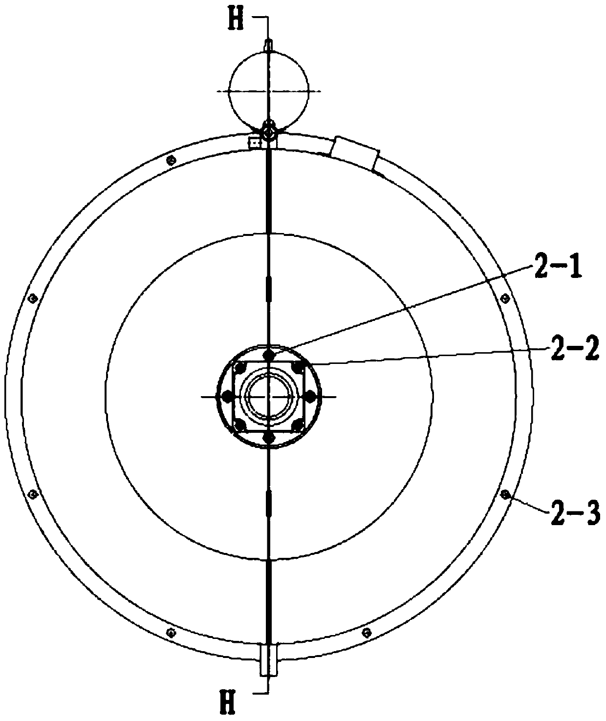
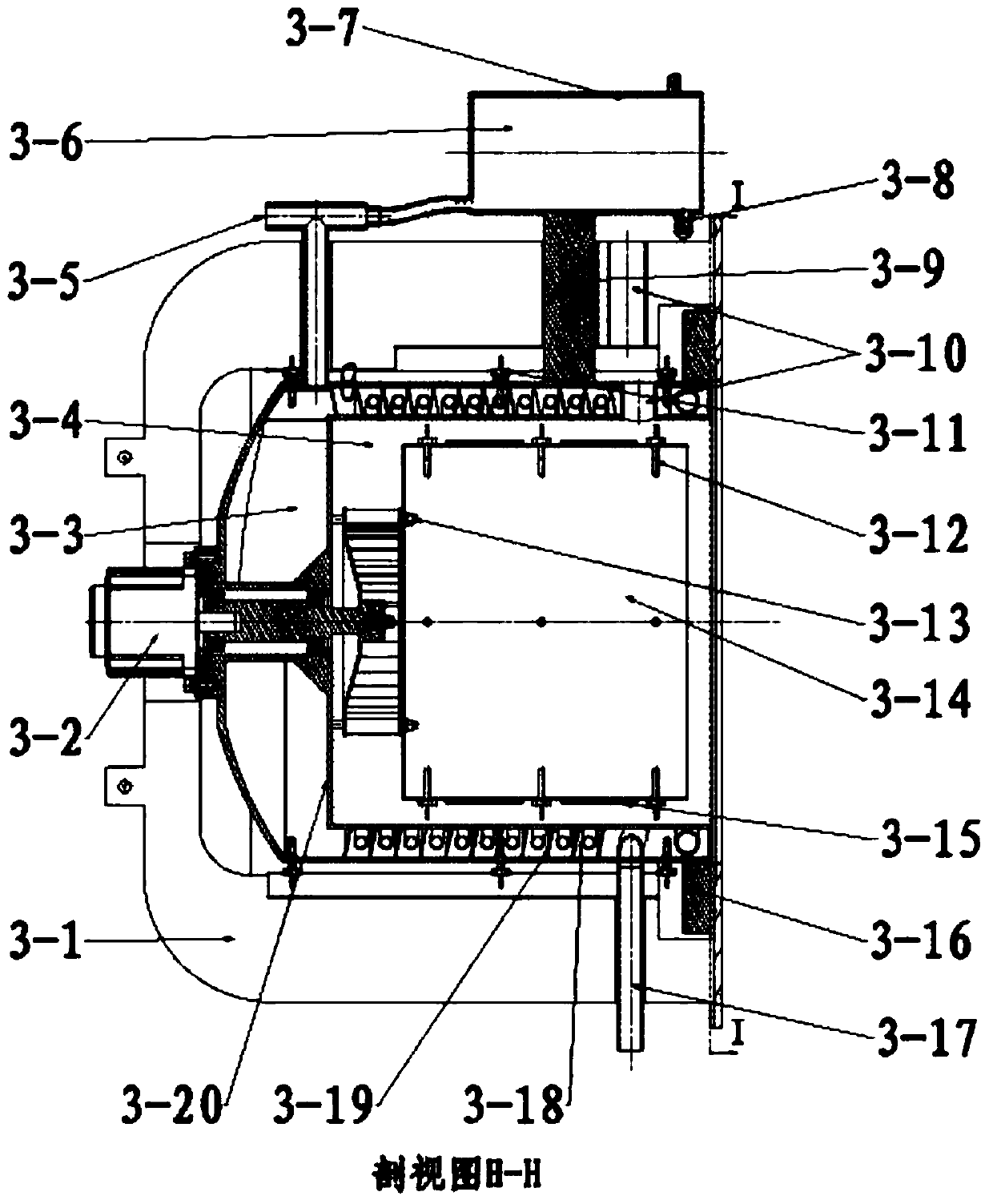
[0025] The invention is a centrifugal-temperature composite test box, which is mainly composed of a main body part of the box, an expansion chamber and a gas circulation system.

[0026] The technical solution of the present invention will be further described below in conjunction with the accompanying drawings.

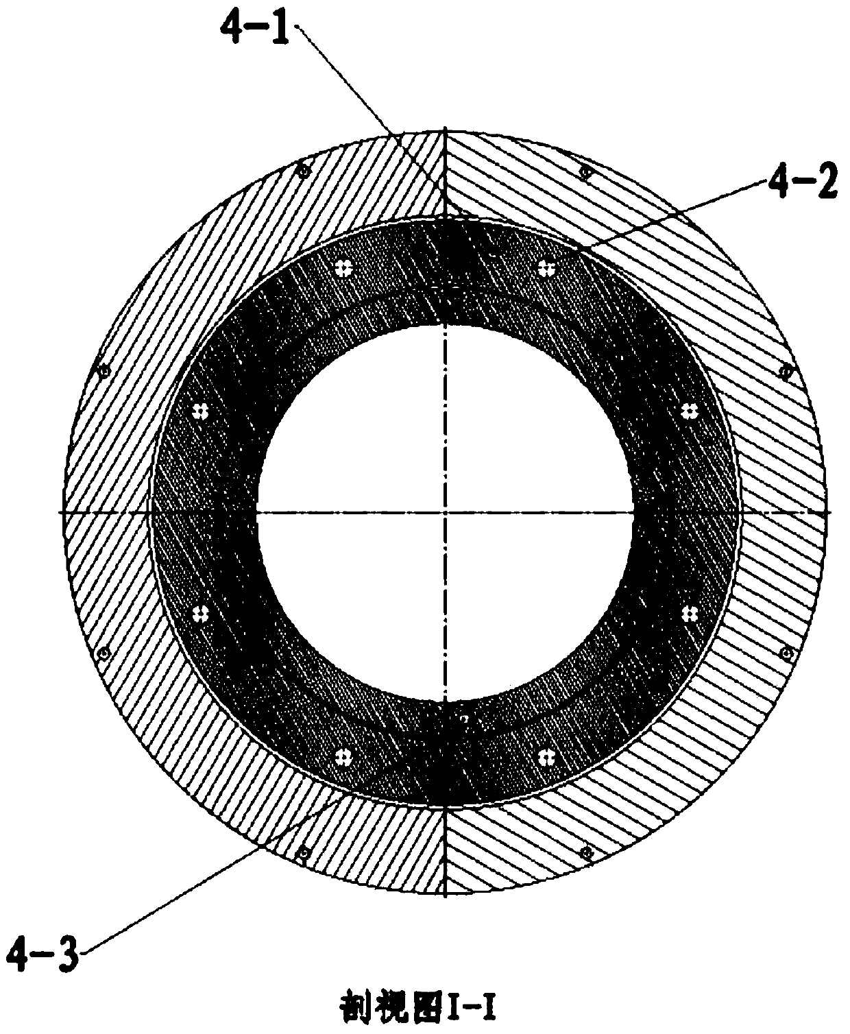
[0027] The structure of the test box is made of 304 stainless steel, and the main part of the box is a cylindrical sandwich structure, which are the insulation layer 3-1, the temperature-carrying layer 3-3, and the inner cavity 3-4.

[0028] Insulation layer 3-1 is a thin cavity formed by two cylindrical surfaces, and the interior is filled with insulation materials. Only one insulation layer is listed in the figure, because the two insulation layers are almost completely symmetrical, but they are a little different from each other because of space issues. The bottoms of the two insulation layers are all fixed to the centrifuge rotating arm 6-2 by the mounting holes ...


PUM


Abstract

The invention is a centrifugal-temperature composite test box, and aims to provide a test box which can be installed and work on a centrifuge and realize a high / low-temperature calibration environment in order to provide a centrifugal-temperature composite calibration environment for an accelerometer. The centrifugal-temperature composite test box is mainly composed of a box body part, an expansion chamber and a gas circulation system. The test box and the accelerometer are separately installed. The box body part is a cylindrical sandwich structure including a heat insulation layer, a temperature carrying layer and an inner cavity. The centrifugal-temperature composite test box is implemented by the following scheme: the heat insulation layer is filled with heat insulation material, the temperature carrying layer is filled with temperature carrying liquid and is equipped with a temperature carrying liquid spiral circulation channel and a temperature carrying gas circulation channel, and the inner cavity is equipped with an air guide sleeve and an electric heating film; the expansion chamber is a closed cavity; the gas circulation system provides power for gas circulation in the cavity; and the temperature of the temperature carrying liquid is controlled directly or controlled by controlling the temperature of gas in the gas pipe, and heat exchange between the inner wall of a temperature carrying cavity and the gas in the inner cavity is utilized or the gas in the inner cavity is heated by the electric heating film so as to realize precise control on the temperature of the inner cavity.

Description

technical field [0001] The invention relates to a centrifugal-temperature compound test chamber, more specifically, it is a test chamber installed and working on a centrifuge, capable of realizing precise control of high and low temperature environments, thereby providing a centrifugal-temperature compound calibration environment for an accelerometer. Background technique [0002] In many application fields, accelerometers need to be calibrated, and a reliable calibration environment needs to be provided. At present, the accelerometer calibration technology for a single standard environment is relatively mature, but because the actual working environment of the accelerometer is very complicated, the calibration of a single environmental parameter Will bring some error. Temperature is an important factor affecting the accuracy of the accelerometer. At present, a test chamber is generally installed on the centrifuge to control the temperature in the test chamber under the rota...

Claims


Application Information

Patent Timeline
IPC IPC(8): G01P21/00
Inventor 孟晓风李颖奇董雪明何畔
Owner BEIHANG UNIV
Learn More