Optical fiber output end fixing device
A fixed device and output technology, applied in the laser field, can solve the problems of fiber deformation, inability to dissipate heat from the fiber, and limit the power of the optical fiber transmission beam, and achieve the effects of high stable pointing and stable and reliable structure.
- Summary
- Abstract
- Description
- Claims
- Application Information
AI Technical Summary
Problems solved by technology
Method used
Image

Examples
Embodiment 1
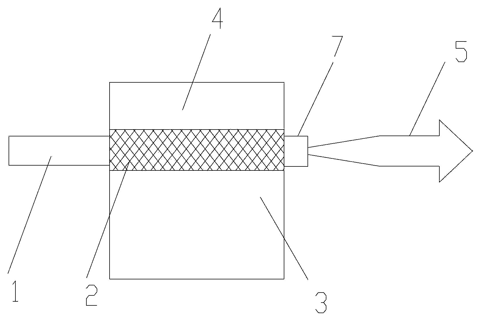
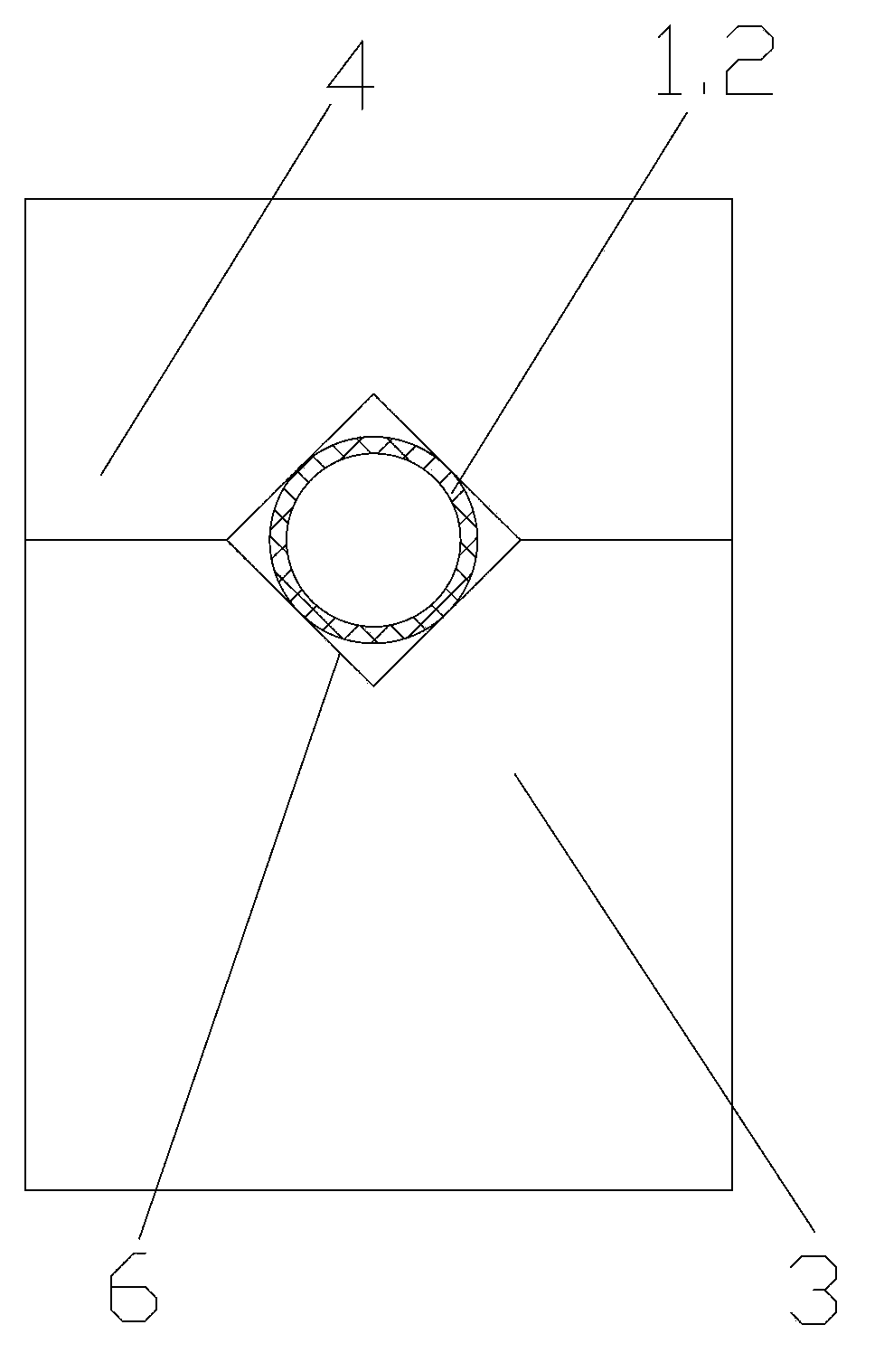
[0027] Such as figure 1 , figure 2 As shown, the optical fiber output end fixing device provided in this embodiment includes: an optical fiber 1 , a metal film 2 , a metal base 3 and a metal pressing block 4 . The optical fiber 1 is an active fiber doped with ytterbium. The output end of the optical fiber 1 is fused with an end cap 7 . The outer surface of the section of the optical fiber 1 fixed in the device is coated with a metal film 2 , specifically, the metal film 2 is a gold film. A V-shaped groove 6 is formed on the metal base 3, and the optical fiber 1 coated with gold film is placed in the V-shaped groove 6, and the gold film and the metal base 3 are fixed together by welding. The metal pressing block 4 is placed above the optical fiber 1 and has a V-shaped groove 6 thereon. The metal pressing block 4 and the metal base 3 are fixed as a whole by screws. Grooving on the metal base 3 and the metal pressing block 4 can increase the contact area between the metal film...
Embodiment 2
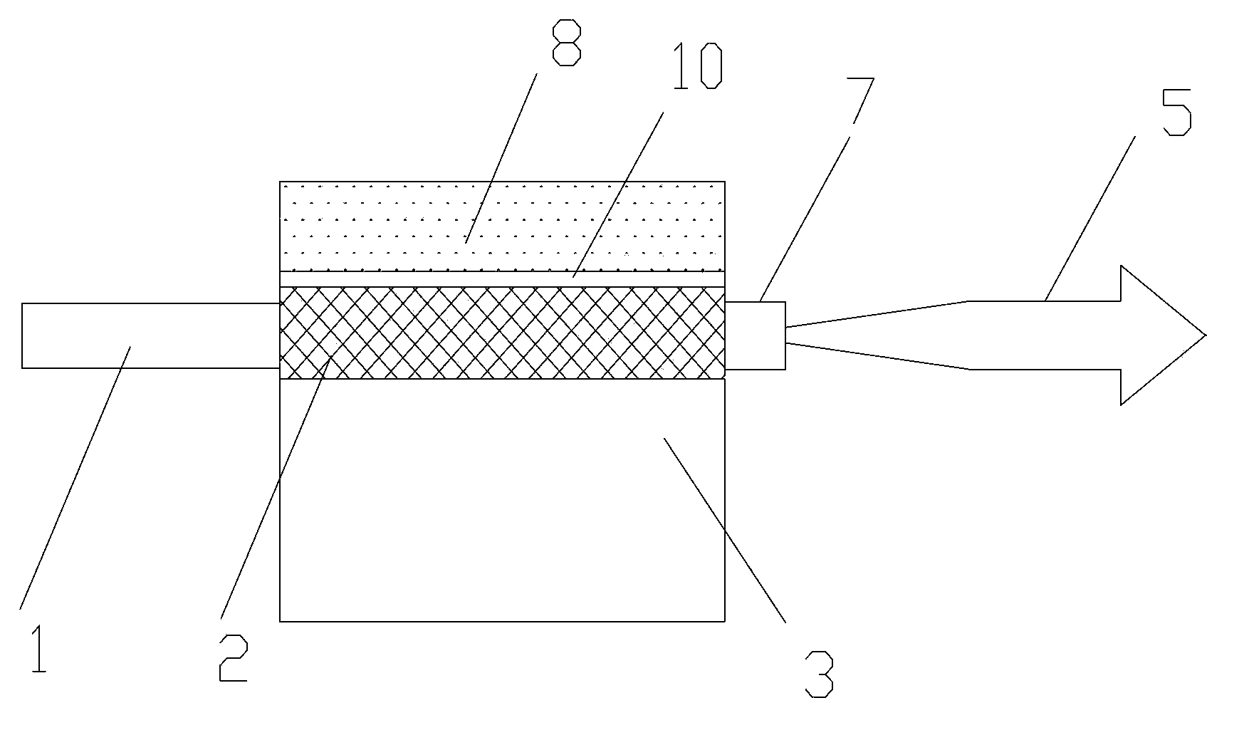
[0030] Such as image 3 , Figure 4 As shown, the optical fiber output end fixing device provided in this embodiment includes: an optical fiber 1 , a metal film 2 , a metal base 3 and a ceramic pressing block 8 . The optical fiber 1 is a passive optical fiber, and the outer surface of a section fixed in the device is covered with a metal film 2, specifically, the metal film 2 is a silver film. The metal base 3 is provided with a U-shaped groove 9, and the optical fiber 1 covered with silver film is placed in the U-shaped groove 9, and the silver film and the metal base 3 are fixed together by bonding. The ceramic compact 8 is placed above the optical fiber 1, and a gasket 10 is placed between the ceramic compact 8 and the optical fiber 1. The gasket 10 can be very thin, soft and elastic, and the gasket 10 can buffer the optical fiber 1 and reduce the pressure. Function: The ceramic pressing block 8 is also provided with a U-shaped groove 9, and the ceramic pressing block 8 a...
Embodiment 3
[0033] Such as Figure 5 , Image 6 As shown, the fiber output end fixing device provided in this embodiment includes: an optical fiber 1 , a metal film 2 and a metal base 3 . The optical fiber 1 is any optical fiber, and the output end of the optical fiber 1 is welded with an end cap 7; the outer surface of a section fixed in the device is coated with a metal film 2, specifically, the metal film 2 is an aluminum film. The metal base 3 is provided with an arc-shaped groove 11, and the optical fiber coated with aluminum film is placed in the arc-shaped groove 11, and the aluminum film 2 and the metal base 3 are fixed together by welding. Grooving on the metal base 3 can increase the contact area between the metal film 2 plated on the outer surface of the optical fiber 1 and the metal base 3 .
[0034] It should be noted that the metal base 3 is used in the embodiment of the present invention to achieve a better heat dissipation effect, but in addition to the metal base 3, it ...
PUM
 Abstract
Description
Claims
Application Information
 - R&D Engineer
- R&D Manager
- IP Professional
- Industry Leading Data Capabilities
- Powerful AI technology
- Patent DNA Extraction
Browse by: Latest US Patents, China's latest patents, Technical Efficacy Thesaurus, Application Domain, Technology Topic.
© 2024 PatSnap. All rights reserved.Legal|Privacy policy|Modern Slavery Act Transparency Statement|Sitemap