

A common-mode voltage suppression method suitable for matrix converter
A matrix converter and common-mode voltage technology, which is applied in the field of control of three-phase matrix converters, can solve problems such as the reduction of the voltage transmission ratio of the converter
Active Publication Date: 2017-01-25
TIANJIN UNIV
View PDF2 Cites 0 Cited by
- Summary
- Abstract
- Description
- Claims
- Application Information
AI Technical Summary
Problems solved by technology
In addition to the above methods, there are also literatures that use the rotation vector of the matrix converter instead of the zero vector to reduce the common-mode voltage, but this method will reduce the voltage transfer ratio of the converter, and the converter topology needs to be further improved to compensate for the voltage Loss of transmission ratio
Method used
View moreImage
Smart ImageViewing Examples

Examples
Embodiment Construction
Login to View More PUM
 Abstract
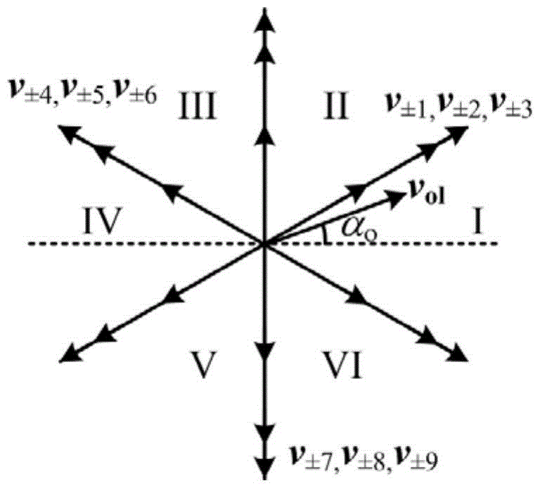
The invention discloses a common-mode-voltage inhibiting method applicable to a matrix converter. An effective vector of the matrix convertor is selected according to a traditional double-voltage modulation method. A pair of large vectors with maximum amplitudes and a pair of intermediate vectors with intermediate vectors on adjacent directions of the effective vector are used to form opposite vectors which are used to substitute a zero vector in a traditional double-voltage modulation method so that an output line voltage is synthesized. A modulation functional expression is constructed on the basis of the traditional double-voltage modulation method so that control demands of input current and output voltage of the matrix converter are met and at the same time, a common-mode voltage amplitude is reduced effectively and it is also ensured that only two ideal switches change when ideal switches of the same output phase are switched. It is proved by experiments that the common-mode-voltage inhibiting method applicable to the matrix converter is capable of reducing a common-mode voltage to 57.7% of an input power-supply amplitude and at the same time, harmonic content of input current and output current is less than that of a current frequently-used optimization zero-vector modulation position method.
Description
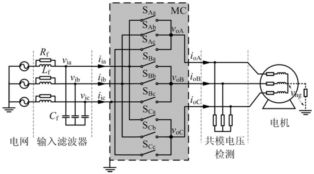
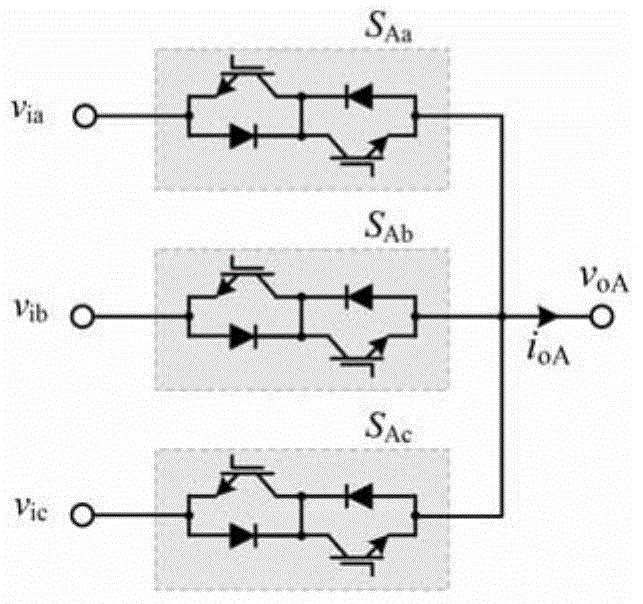
A common-mode voltage suppression method suitable for matrix converter technical field The invention belongs to the field of power converter control for driving motors, in particular to a control method for a three-phase matrix converter under dual-voltage modulation, which is used to reduce the amplitude of the common-mode voltage generated during the modulation process and slow down the damage caused by the common-mode voltage to the motor bearings. Damage and EMI problems. Background technique When the pulse width modulation signal acts on the bidirectional switch of the matrix converter, a high-frequency common-mode voltage will be generated between the neutral point of the load and the reference ground. The common mode voltage will form the shaft voltage from the shaft to the bearing seat through the distributed capacitance between the stator, rotor, air gap and the ground of the motor. When the shaft voltage overcomes the resistance of the bearing oil film, a shaft c...
Claims
Login to View More Application Information
Patent Timeline
 Patent Type & AuthorityPatents(China)
IPC IPC(8): H02M5/22
Inventor阎彦黄启勇史婷娜夏长亮
OwnerTIANJIN UNIV