Combine
A combine harvester and grain technology, applied in agricultural machinery and implements, threshing equipment, agriculture, etc., can solve the problems affecting the output of the grain amount detection sensor, and achieve the effect of improving the detection accuracy
- Summary
- Abstract
- Description
- Claims
- Application Information
AI Technical Summary
Problems solved by technology
Method used
Image
Examples
Embodiment approach 1
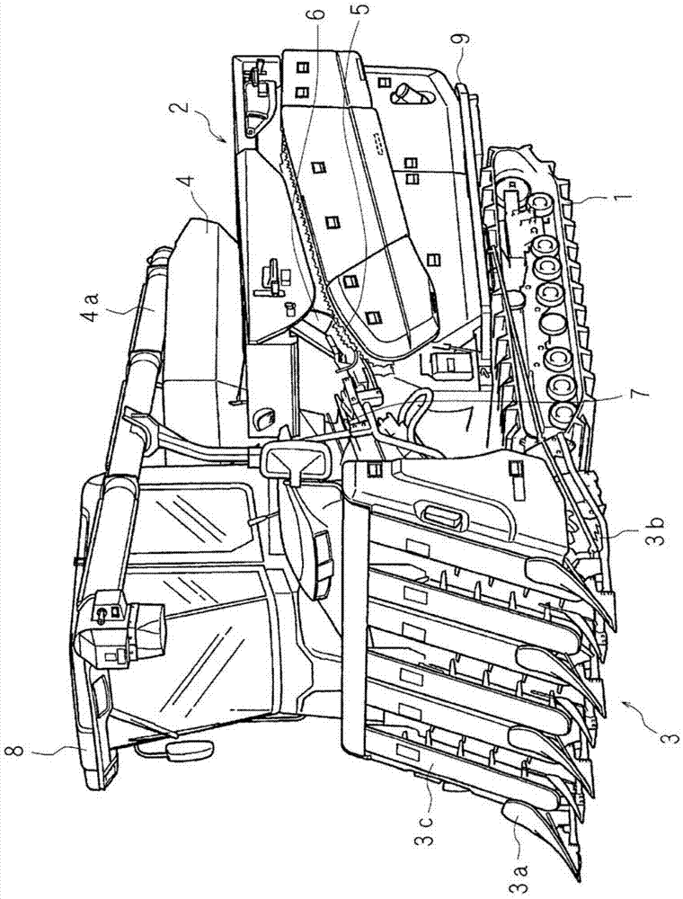
[0087] Hereinafter, this invention is demonstrated in detail based on drawing which shows the combine which concerns on Embodiment 1. FIG. figure 1 It is a three-dimensional view of the appearance of the combine harvester.
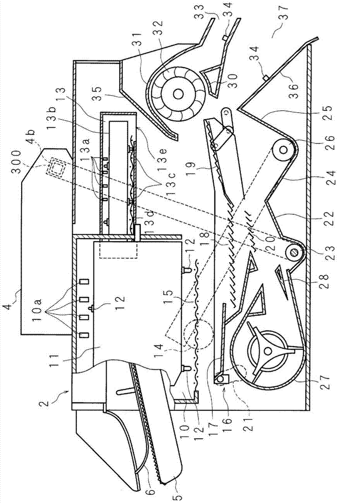
[0088] In the figure, 1 denotes a traveling crawler, and an organic body 9 is provided on the upper side of the traveling crawler 1 . A threshing device 2 is arranged above the machine body 9 . On the front side of the threshing device 2, a harvesting part 3 is provided, and the harvesting part 3 has a grass dividing board 3a for distinguishing harvested grain stems and non-harvested grain stems, a cutting knife 3b for harvesting grain stems, and a mechanism for pulling up grain stems. The pull-up device 3c. On the right side of the threshing device 2, a grain box 4 for storing grains is provided, and on the left side of the threshing device 2, a long feed chain 5 is provided along the front-back direction of conveying grain stalks.
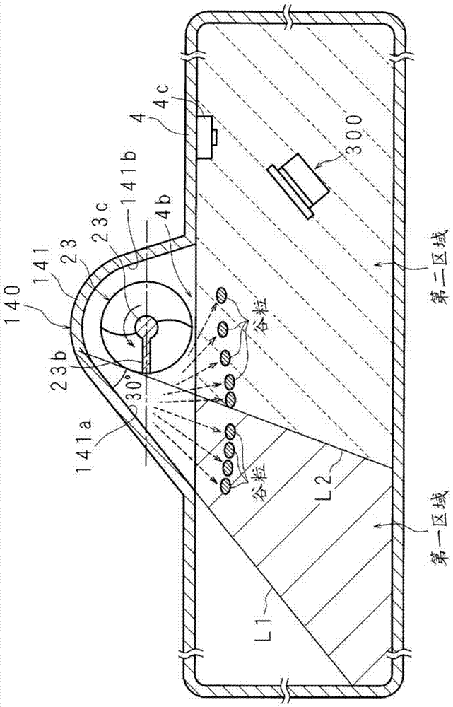
[0089] The upper s...
Embodiment approach 2
[0170] Hereinafter, this invention is demonstrated in detail based on drawing which shows the combine which concerns on Embodiment 2. FIG. Figure 12 It is an example of the graph which shows the relationship between the detection value of the inlet sensor 300 and the detection value of the pickup sensor 51. Figure 12 A is a graph showing the relationship between time and the detection value of the inlet sensor 300 . The detection value of the inlet sensor 300 shows the strain amount by the collision of a grain, and is a moving average in the predetermined sampling number. Figure 12 B is a graph showing the relationship between time and the detection value of the pickup sensor 51 . The detection value of the pick-up sensor 51 shows the rotation start time and the rotation end time of one rotation of the blade plate 23b.
[0171] CPU100a compares the detection value input from the inlet sensor 300 in P / 4 - 3P / 4 period, and threshold-value α. Among the detected values inp...
Embodiment approach 3
[0182] Hereinafter, this invention is demonstrated in detail based on drawing which shows the combine which concerns on Embodiment 3. FIG. Figure 14 It is a longitudinal cross-sectional view schematically showing the inlet sensor 300 . Figure 14 A represents the inlet sensor 300 at an appropriate position, Figure 14 B represents the inlet sensor 300 at a position shifted from the proper position.
[0183] The inlet sensor 300 has a sensor body 301 (fixed portion) provided with a strain gauge, a circuit board, and the like. The sensor main body 301 has a housing, and a strain gauge, a circuit board, and the like are accommodated in the housing. The back of the frame of the sensor main body 301 is fixed to the supporting member 310 by a plurality of screws 311 . In addition, the sensor main body 301 should just be the structure which can detect the impact value of the grain which collided. For example, instead of strain gauges, piezoelectric elements may be used.
[0184...
PUM
 Abstract
Description
Claims
Application Information
 - R&D
- Intellectual Property
- Life Sciences
- Materials
- Tech Scout
- Unparalleled Data Quality
- Higher Quality Content
- 60% Fewer Hallucinations
Browse by: Latest US Patents, China's latest patents, Technical Efficacy Thesaurus, Application Domain, Technology Topic, Popular Technical Reports.
© 2025 PatSnap. All rights reserved.Legal|Privacy policy|Modern Slavery Act Transparency Statement|Sitemap|About US| Contact US: help@patsnap.com


