Inhaler component

A technology of inhalers and components, which is applied in the direction of inhalers, respirators, and medical devices, and can solve the problems of large and limited inhaler components

Inactive Publication Date: 2014-05-07
BATMARK
View PDF5 Cites 20 Cited by
  • Summary
  • Abstract
  • Description
  • Claims
  • Application Information

AI Technical Summary

Problems solved by technology

This arrangement proves to be particularly space demanding and leads to relatively large dimensions of the inhaler assembly
Another disadvantage is that the capillary gap 41 is extremely limited in its flat extension, if a negative pressure occurs by the gravity of the liquid column acting in the capillary in the reservoir 45 when the capillary gap is in a vertical position , the negative pressure must be compensated by the capillary action of the vent channel 52
However, if the capillary action of the ventilation channel 52 is no longer sufficient to maintain equilibrium, then all the liquid material 16 in the liquid container 4 has the possibility of flowing out via the capillary gap 41

Method used


Image

  • Inhaler component
  • Inhaler component
  • Inhaler component

Examples


Embodiment Construction

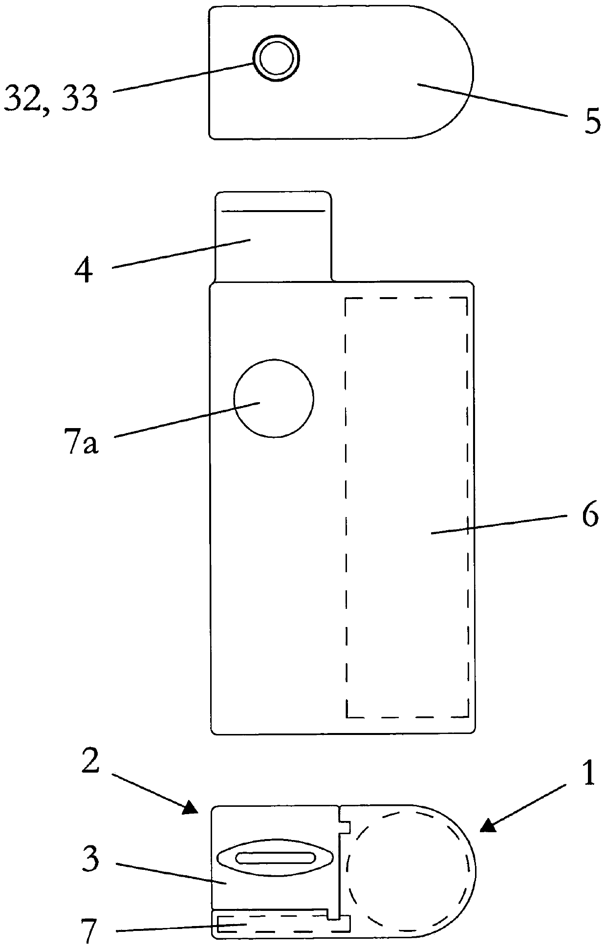
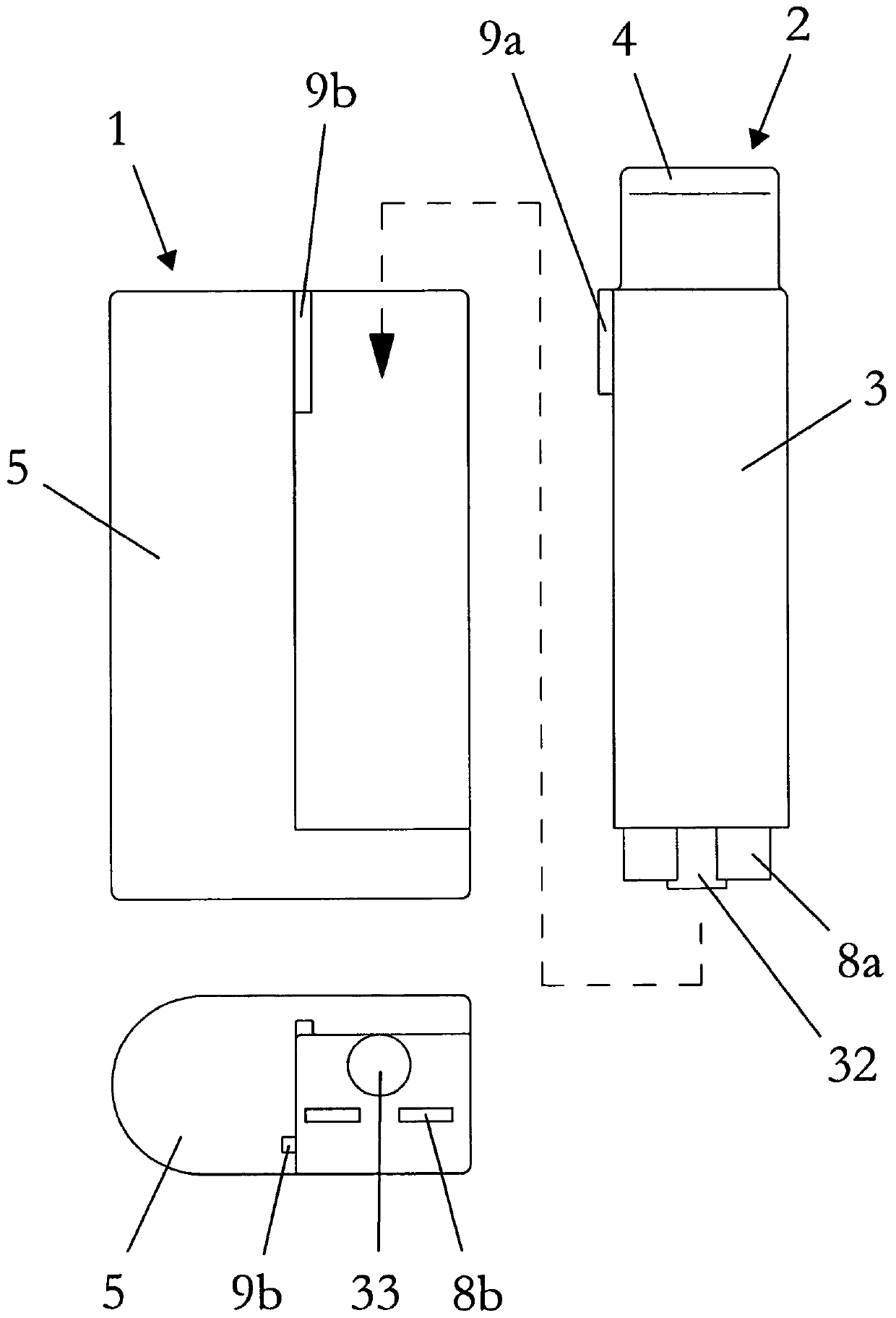
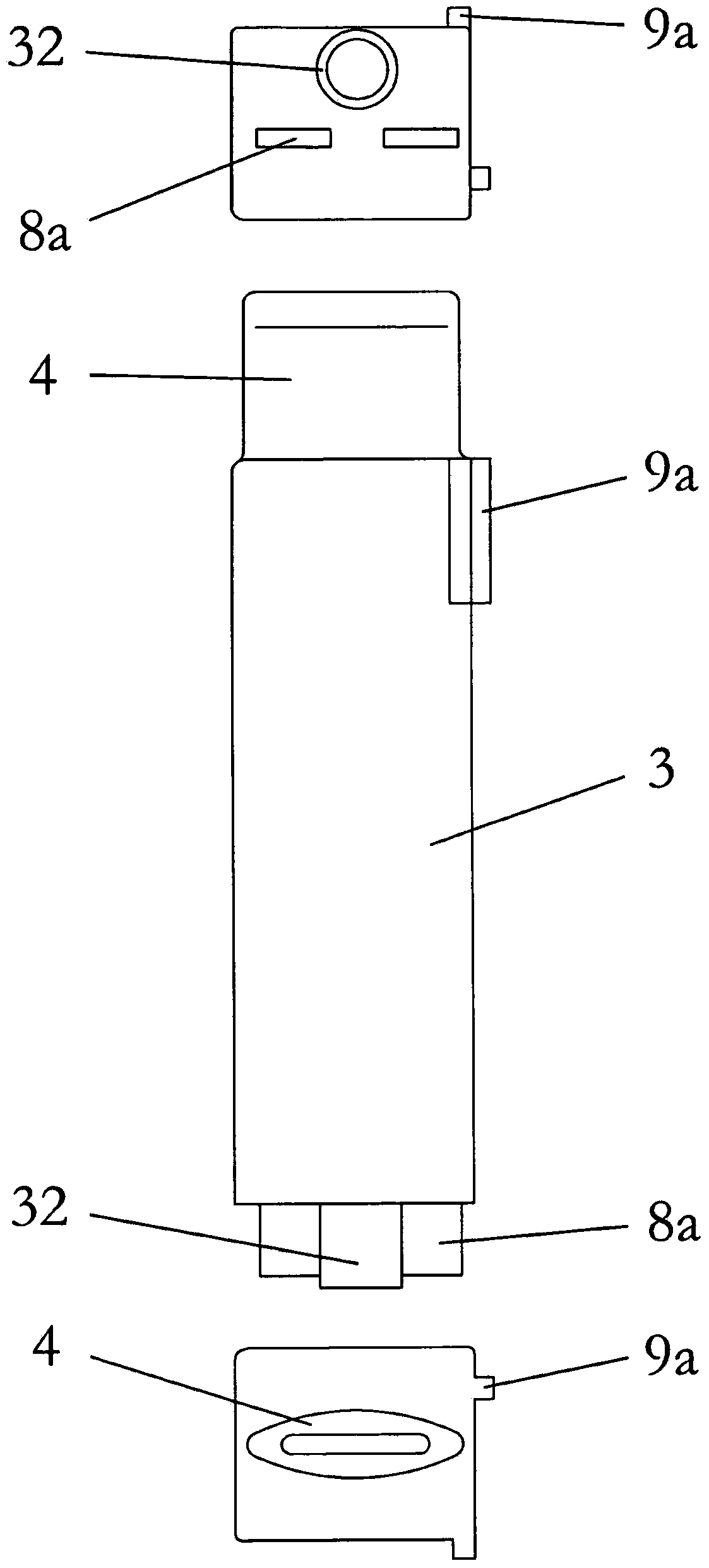
[0029] figure 1 An inhaler according to the invention is shown which is shaped and dimensioned such that the inhaler can be handled easily and comfortably by the user. The inhaler is only roughly half the size of a cigarette pack in terms of volume. In principle, the inhaler shown as an example consists of two parts, namely the inhaler part 1 and the inhaler assembly 2 .

[0030] The inhaler assembly 2 is formed by a housing 3 , which forms a pipe-shaped mouthpiece 4 on the end side. Housing 3 is preferably made of plastic. The inhaler assembly 2 contains liquid material that is electrovaporized within the housing 3 and converted into an inhalable vapor-air mixture and / or condensed aerosol. The resulting vapor-air mixture and / or condensed aerosol is supplied to the user via the mouthpiece 4 . In principle, all substances and preparations which evaporate under atmospheric conditions with as little residue as possible can be considered as liquid materials. This condition i...


PUM

PropertyMeasurementUnit
widthaaaaaaaaaa

Abstract

The invention relates to an inhaler component for forming a vapor-air mixture or/and condensation aerosol by evaporation of a liquid material (18) and, if appropriate, condensation of the formed vapor. The inhaler component comprises: an electric heating element for evaporating a portion of the liquid material (18); a wick with a capillary structure, which forms a composite (10) with the heating element and automatically supplies the heating element with the liquid material (18); a carrier plate (11), preferably a printed circuit board, which carries the composite (10) and on which the heating element is electrically contacted; a capillary gap (16) formed at least partially by the carrier plate (11) and automatically supplying the composite (10) with the liquid material (18), by means of an end portion of the wick extending into the capillary gap (16); and a liquid container (19) which contains the liquid material (18) and from which the capillary gap (16) draws the liquid material (18). In order to achieve a compact overall arrangement, it is proposed that the capillary gap (16) at least partially covers the liquid container (19) on the outside, in a view perpendicular to the carrier plate (11).

Description

technical field [0001] The present invention relates to an inhaler assembly for forming a vapor-air mixture and / or condensing an aerosol by evaporating a liquid material and if necessary condensing the formed vapor, comprising: [0002] Electric heating elements for evaporating a portion of the liquid material; [0003] A wick with a capillary structure, which forms a Verbund with the heating element and automatically supplies the heating element with liquid material; [0004] a carrier plate, preferably a circuit board, carrying the assembly and on which the heating element is electrically contacted; [0005] a capillary gap formed at least in part by the carrier plate for automatically supplying the assembly with liquid material when the end section of the wick penetrates into the capillary gap; [0006] A liquid container containing a liquid material from which the capillary gap draws the liquid material. Background technique [0007] In the specific patent application...

Claims


Application Information

Patent Timeline
Patent Type & Authority Applications(China)
IPC IPC(8): A24F47/00A61M15/06A24F40/10A24F40/42A24F40/44A24F40/485
CPCA61M11/042A61M16/109A61M16/145A61M11/041A61M15/06A61M2205/8206A24F40/42A24F40/46A24F40/10A24F40/44A24F40/485A61M15/0021A61M2205/12A61M2205/583
Inventor 赫尔穆特·布赫贝格尔
Owner BATMARK
Why Eureka
Try Eureka