Supercharge Your Innovation With Domain-Expert AI Agents!

Valve system for a gas engine

A technology of gas engine and engine, applied in the field of valve system, can solve the problem that the control valve cannot rotate, etc.

Active Publication Date: 2014-05-07
BERGEN ENGINES
View PDF13 Cites 3 Cited by
  • Summary
  • Abstract
  • Description
  • Claims
  • Application Information

AI Technical Summary

Problems solved by technology

FR 2354447A shows a linearly movable supply valve and surrounding control valve, but where the control valve cannot rotate

Method used


Image

  • Valve system for a gas engine
  • Valve system for a gas engine

Examples


Embodiment Construction

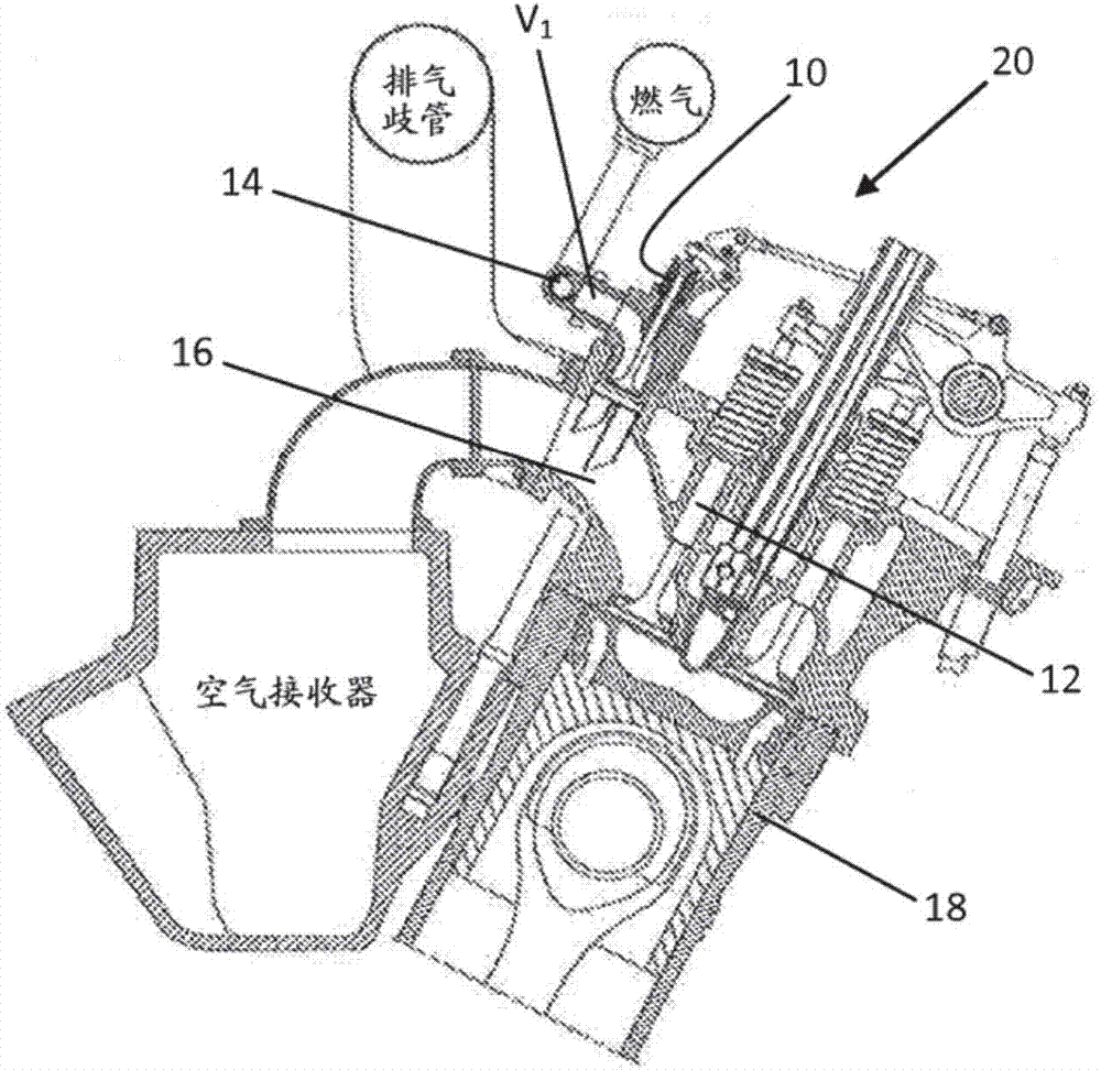
[0025] Gas engines are considered known to those skilled in the art, and therefore are not described in more detail in this application. However, will figure 1 It is shown to illustrate known constructions of valves according to what has been described above. Here, a control valve 10 is arranged in an engine 20 and adjoins an intake manifold 16 which extends further to an intake valve 12 for further admission of gases into cylinders 18 of the engine. Furthermore, an air supply valve 14 is placed in the air inlet for making the occupied volume V 1 The gas enters between the control valve and the supply valve. This gas expands from the main gas pressure to the pressure of the intake manifold 16 through the control valve and is not controlled by the control valve as described. In known gas engines, the volume V 1 Usually about 120cm 3 .

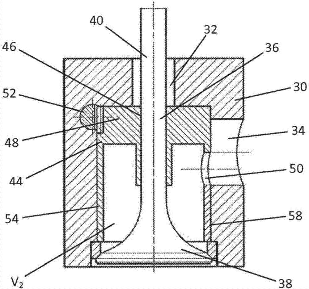
[0026] next combine figure 2 The basic aspects and technical features of the gas engine according to the invention are explained in mor...


PUM


Abstract

A valve system is described for a gas engine (20) comprising a number of valves (36, 44) that are arranged to regulate the amount and supply of gas into an inlet manifold (16) in the engine (20). The system comprises a valve housing (30) equipped with a centrally placed and linearly moving control valve (36) and a surrounding admission valve (44), where the admission valve (44) is arranged to rotate to regulate the amount of gas that is let into the valve housing (30).

Description

technical field [0001] The invention relates to a valve system for a gas engine comprising a plurality of valves arranged to regulate the quantity and supply of gas into an intake manifold in the engine. Background technique [0002] The invention generally relates to a valve control device for a lean-burn gas engine, even though the invention can in principle also be used in other gas engines. In a lean-burn gas engine (Otto engine), the cylinders are filled with a homogeneous, lean mixture of air and fuel gases. To achieve a stable and safe ignition of the charge, an ignition enhancement device in the form of a pre-chamber is usually used, in which the charge is richer due to the fuel gas being supplied through a separate pre-chamber gas valve and in which An ignition device in the form of a spark plug or a pilot injection valve is arranged in the pre-chamber. In this respect, it is important to capture as little as possible the relative amount of energy released in the ...

Claims


Application Information

Patent Timeline
Patent Type & Authority Applications(China)
IPC IPC(8): F01L5/08F01L5/10F01L7/02F01L7/06F02B19/10
CPCF01L1/443F01L3/085F01L5/18F01L7/024F02M21/0236F02M21/0239F02M21/04F23C13/08F23C99/00F23C2900/99008F23C2900/9901Y02E20/34Y02T10/30
Inventor 约翰·埃纳尔·霍韦穆恩埃伦德·瓦克特舍尔德
Owner BERGEN ENGINES
Features
  • R&D
  • Intellectual Property
  • Life Sciences
  • Materials
  • Tech Scout
  • Unparalleled Data Quality
  • Higher Quality Content
  • 60% Fewer Hallucinations
Learn More