Photovoltaic module

A photovoltaic module and control unit technology, applied in the field of photovoltaic modules, can solve the problems of non-isolation

Inactive Publication Date: 2014-05-07
ESYZZ UG HAFTUNGSBESCHRANKT
View PDF9 Cites 12 Cited by
  • Summary
  • Abstract
  • Description
  • Claims
  • Application Information

AI Technical Summary

Problems solved by technology

The problem is also encountered here that isolation i

Method used


Image

  • Photovoltaic module
  • Photovoltaic module
  • Photovoltaic module

Examples


Embodiment Construction

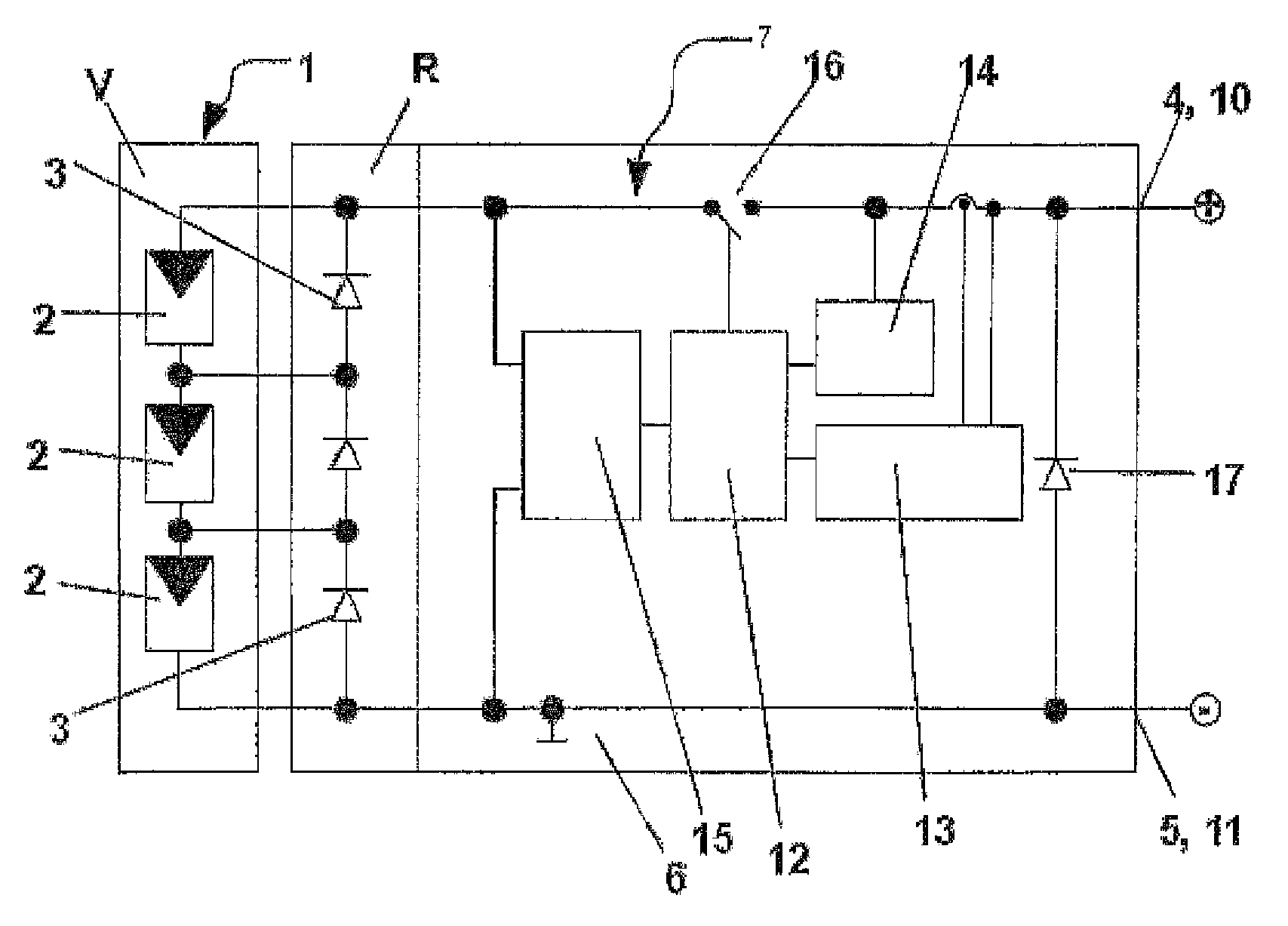
[0026] in figure 1 The first embodiment of the present invention is shown in. Here, a photovoltaic module 1 is schematically shown, which has three solar cells 2 on its front side V, which are wired in series in a string. The terminals of the solar cell 2 are led to the back R of the photovoltaic module 1 on which the bypass diode 3 is arranged, which ensures the current through the string even when the solar cell 2 fails. The voltage output terminals 4 and 5 of the photovoltaic module 1 are led out from the back R. The bypass diode 3 and the voltage output terminals 4, 5 are arranged in a junction box 6, which can be accessed from the back R. A module 7 is arranged locally in the photovoltaic module 1. The assembly 7 includes two voltage input terminals 8, 9 and two voltage output terminals 10, 11. In addition, the assembly 7 includes an analysis and control unit 12, a measuring device 13, a testing device 14, an internal voltage source 15, a switching element 16 and a diod...


PUM


Abstract

The invention relates to a photovoltaic module (1), comprising at least one solar cell (2) and a socket outlet (6), wherein the socket outlet (6) has the voltage outputs (4, 5) of the photovoltaic module (1). An evaluation and control unit (12), which detects a voltage (UA) and/or a current (IA) of the photovoltaic module (1), is arranged in or on the socket outlet (6) as an assembly (7). At least one switching element (16) is associated with the photovoltaic module (1), the switching element being actuable by the evaluation and control unit (12). The photovoltaic module (1) can be disconnected by means of the switching element (16). The evaluation and control unit (12) is designed in such a way that, on the basis of the detected voltage (UA) and/or the detected current (IA), a fault state can be detected and the switching element (16), on the basis of the detected fault state, can be actuated by the evaluation and control unit (12) in order to disconnect or short-circuit at least one of the voltage outputs (4, 5; 10, 11) of the photovoltaic module (1) or the assembly (7).

Description

Technical field [0001] The invention relates to a photovoltaic module according to the preamble of claim 1. Background technique [0002] The photovoltaic module includes at least one solar cell and a junction box, wherein the junction box has a voltage output terminal of the photovoltaic module. Usually photovoltaic modules have a plurality of solar cells which are wired in series and / or in parallel in a so-called string, wherein both ends of the string are then led to a junction box. In known solar installations, multiple photovoltaic modules can then also be wired in one or more strings. [0003] In the case of a fire in a house or house, the fire brigade must try to connect the place of use without current and voltage so that, for example, in the case of using a fire extinguishing device, it will not be injured by electric shock or arc. [0004] DE 10 2005 018 173 A1 discloses a method for the safe operation interruption of photovoltaic installations with a protection device wh...

Claims


Application Information

Patent Timeline
IPC IPC(8): H02S50/10H02S40/30
CPCH01L31/02021H02H3/023H02H3/087H02H3/12H02S50/00H02S50/10Y02E10/56
Inventor D.贝格
Owner ESYZZ UG HAFTUNGSBESCHRANKT
Why Eureka
Try Eureka