Soil box soil deep vibration compactor

A technology of shaking and soiling, which is used in devices for loosening soil, agricultural machinery and implements, suppressors, etc. It can solve the problems of not adapting to the requirements of soil deep loosening experiments, high work intensity, and low firmness.

Inactive Publication Date: 2014-05-14
NORTHWEST A & F UNIV
View PDF5 Cites 3 Cited by
  • Summary
  • Abstract
  • Description
  • Claims
  • Application Information

AI Technical Summary

Problems solved by technology

[0002] The plow layer of the soil becomes shallower, severely hardened, and the hardness of the plow bottom layer increases, which seriously restricts the comprehensive production capacity of the land. The characteristic of this kind of soil is that the firmness of the deep layer is much higher than that of the upper layer. These methods can only compact the surface soil, and the deeper the depth, the smaller the firmness. Among them, the effective compaction depth of smooth rolling is ≤100mm, and the effective depth of vibration compaction is ≤250mm, which are not suitable for soil. According to the experimental requirements of subsoiling in the soil tank, the only way to effectively control the firmness of soil at different depths is manual compaction, but its work intensity is too high

Method used


Image

  • Soil box soil deep vibration compactor
  • Soil box soil deep vibration compactor
  • Soil box soil deep vibration compactor

Examples


Embodiment 1

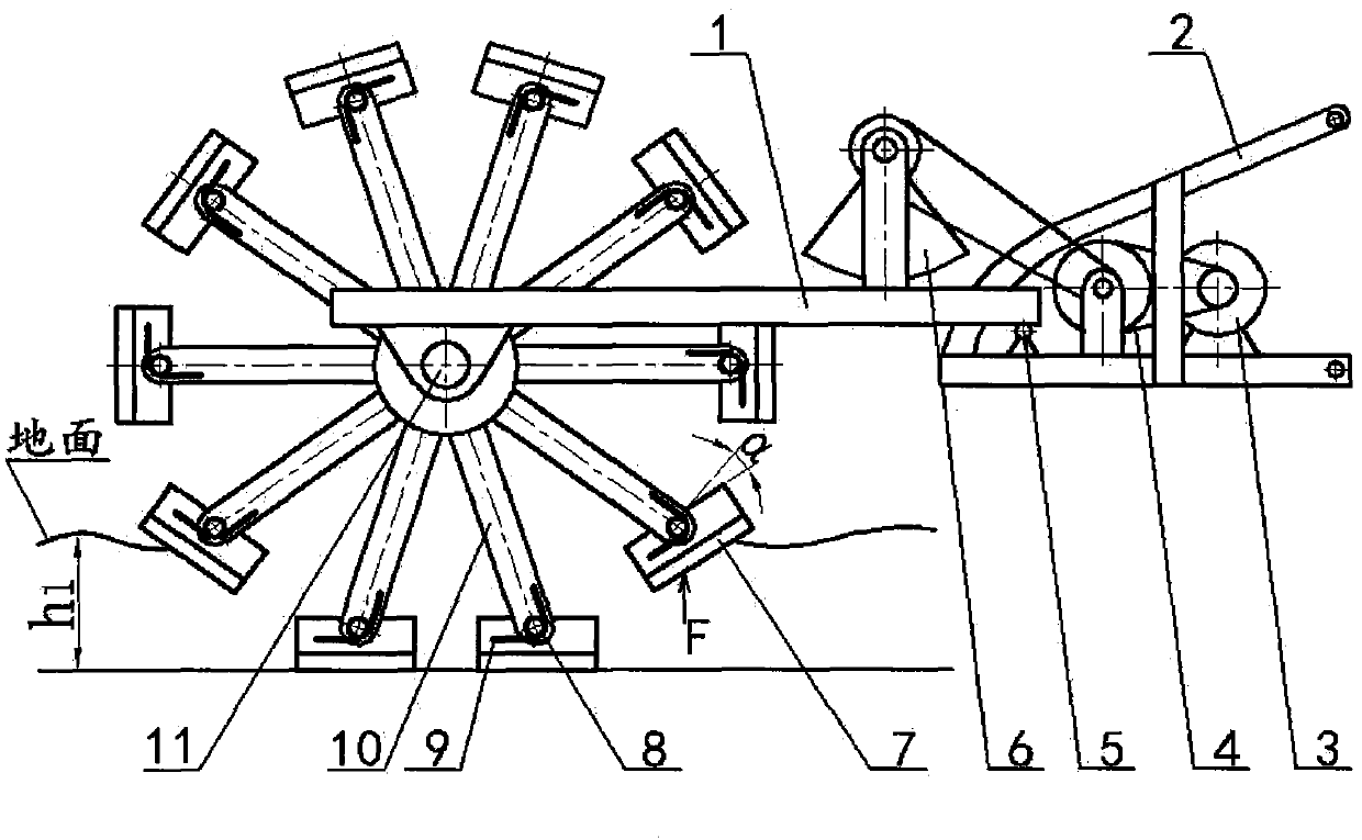
[0014] Embodiment 1: A compacting machine in which several tamping wheels work separately

[0015] Such as figure 1 and figure 2 Shown, the surface area of ​​each tamping hammer tup of a single tamping wheel is relatively small, and the pressure on the soil is relatively large, so it can go deep into the soil and compact the soil.

Embodiment 2

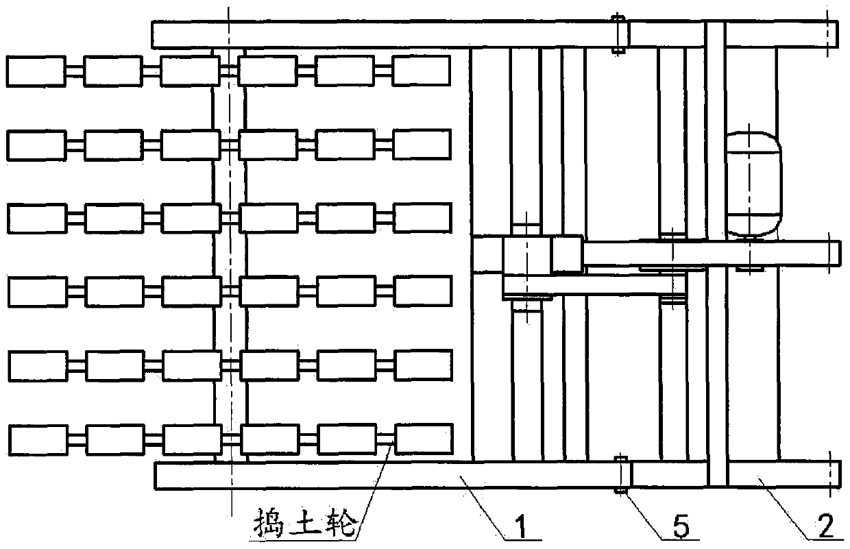
[0016] Embodiment 2: A compacting machine in which a plurality of tamping wheels are combined to work

[0017] Such as image 3 As shown, multiple ramming wheels ( image 3 Shown as two) combined together, can increase the surface area of ​​the tamping hammer tup, the pressure of the soil on the tup reduces, and the tup can only go deep into the shallower part of the soil for compaction.

Embodiment 3

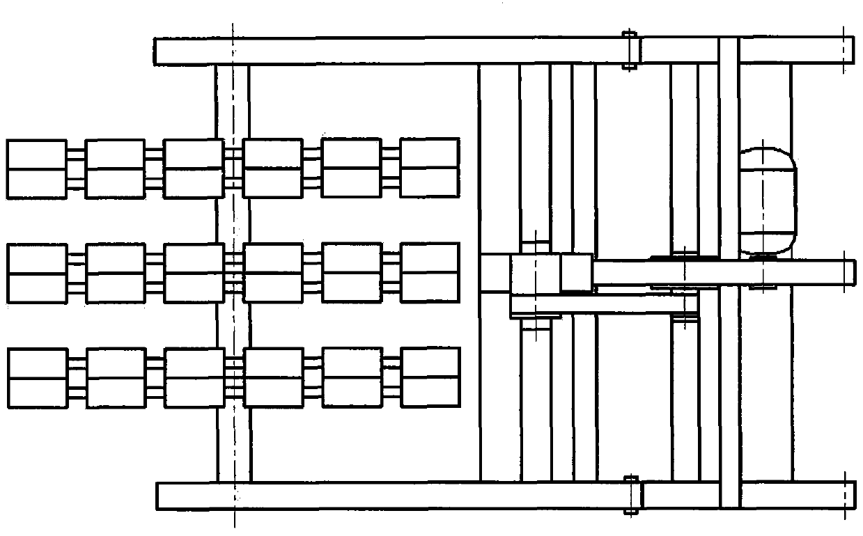
[0018] Embodiment 3: A vibrating machine with different diameter tamping wheels working in combination

[0019] Such as Figure 4 As shown, the tamping wheel in this embodiment three includes a large-diameter tamping wheel and a small-diameter tamping wheel, which can realize the simultaneous vibration of the upper and lower layers of soil with different depths.


PUM


Abstract

The invention belongs to the field of agricultural machines, and relates to a soil box soil deep vibration compactor to solve the problem that an existing compactor only can compress the surface soil with a certain thickness. According to the soil box soil deep vibration compactor, a soil box trolley drags soil beating wheels to advance through a hanging machine frame (2) and a vibrating machine frame (1), meanwhile, a motor (3) drives an eccentric vibration block (6) through a belt transmission system (4) to enable the soil beating wheels to vibrate around a pivot (5) along with the vibrating machine frame (1), the surface area of a hammer (7) of the soil beating wheel is small, and the hammers (7) can go deep into the soil by h1 to vibrate and compress the soil through the impact of gravity and vibration. The shapes of soil touch plane structures of the soil beating hammers are random, if the structure is designed into a thin strip shape, and a long edge is perpendicular to a soil beating axle (11), the hammer rotates around a small hammer shaft (8) by an angle alpha through the action of the force F, and the surfaces of the hammers press the soil downwards as much as possible. After the hammers separate from the soil, the hammers are reset through reset springs (9) and are perpendicular to hammer rods (10). The diameters of the soil beating wheels can be different, and the soil beating wheels can be combined or separated along the soil beating axle (11) to adapt to the vibration compacting of soil of different depths.

Description

technical field [0001] The invention relates to a machine for finishing soil in a soil tank, which belongs to the field of agricultural machinery. Specifically, it relates to a deep vibrating machine for soil in a soil tank. Background technique [0002] The plow layer of the soil becomes shallower, severely hardened, and the hardness of the plow bottom layer increases, which seriously restricts the comprehensive production capacity of the land. The characteristic of this kind of soil is that the firmness of the deep layer is much higher than that of the upper layer. These methods can only compact the surface soil, and the deeper the depth, the smaller the firmness. Among them, the effective compaction depth of smooth rolling is ≤100mm, and the effective depth of vibration compaction is ≤250mm, which are not suitable for soil. According to the requirements of subsoiling experiments in soil tanks, the only way to effectively control the soil firmness at different depths is m...

Claims


Application Information

Patent Timeline
Patent Type & Authority Applications(China)
IPC IPC(8): A01B29/04A01B37/00
Inventor 杨有刚杨光武鸣放张炜李敏通冯涛张淑伟韩超郭康权刘建星王旭财张建辉刘宝选卫武权
Owner NORTHWEST A & F UNIV
Why Eureka
Try Eureka