
Laser three-point dynamic positioning method and system thereof

A dynamic positioning and laser technology, used in positioning, radio wave measurement systems, measurement devices, etc., can solve the problems of positioning accuracy, reliability decline, precise positioning of immovable objects, and poor long-distance positioning accuracy. The effect of reducing cumulative error and high positioning accuracy

Inactive Publication Date: 2010-03-17
HUNAN AGRICULTURAL UNIV
View PDF3 Cites 33 Cited by
  • Summary
  • Abstract
  • Description
  • Claims
  • Application Information

AI Technical Summary

Problems solved by technology

Generally speaking, the high-precision GPS positioning system is complex and expensive, while the lower-priced GPS system has insufficient positioning accuracy and cannot accurately locate moving objects; radio positioning is related to the propagation of radio waves, so in a certain To a certain extent, it is affected by climate, terrain, location and electromagnetic interference; visual positioning has the advantages of wide information detection range and complete target information, but the long-distance positioning accuracy is poor and is greatly affected by harsh environments; inertial sensor is an autonomous The positioning method completely relies on the equipment to complete the positioning task independently, and the work is not limited by weather conditions. The positioning accuracy is high in a short period of time, and there is a cumulative error when working for a long time, and the positioning accuracy and reliability will decrease.

Method used


Image

  • Laser three-point dynamic positioning method and system thereof
  • Laser three-point dynamic positioning method and system thereof
  • Laser three-point dynamic positioning method and system thereof

Examples


Embodiment 1

[0031] The laser three-point dynamic positioning system consists of two base stations and a mobile master station.

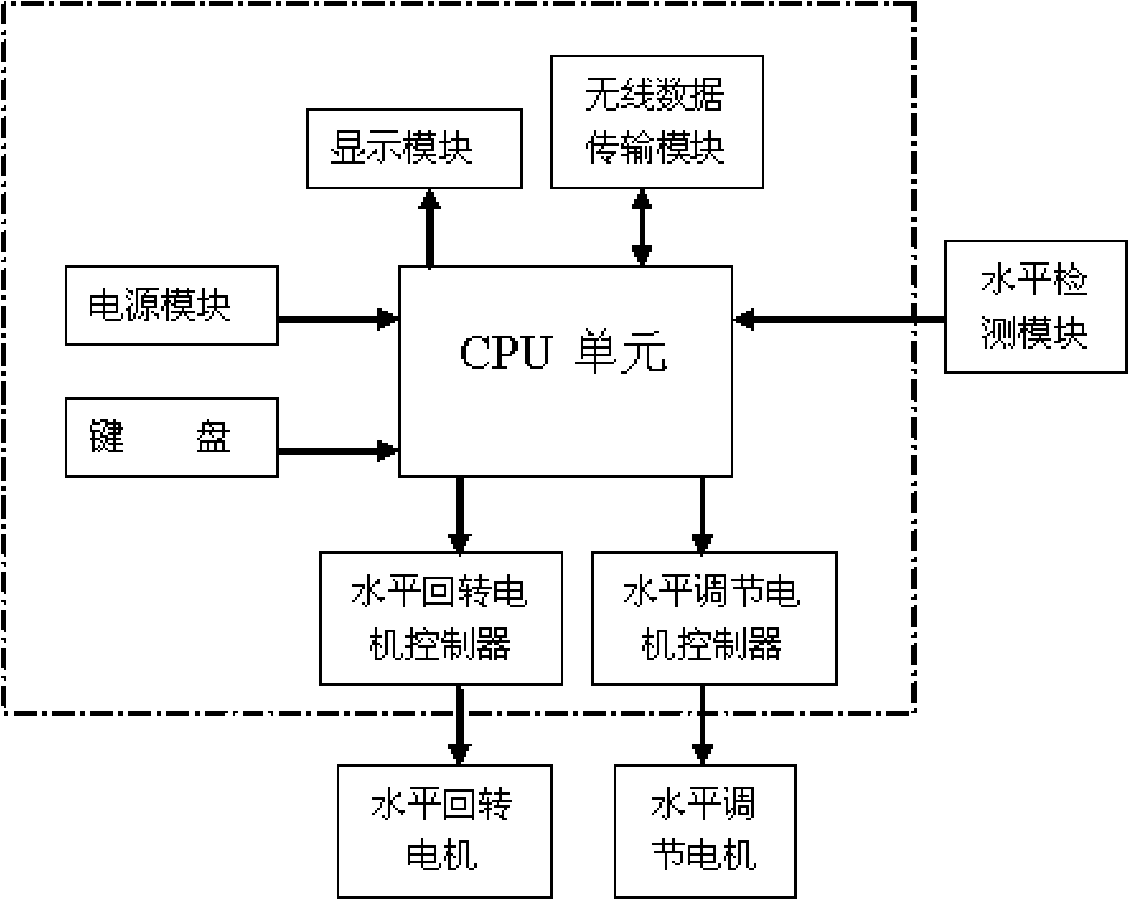
[0032] The two base stations are respectively composed of a laser transmitter, a horizontal rotary platform, a horizontal rotary angle measurement module, a horizontal detection module and a base station controller.

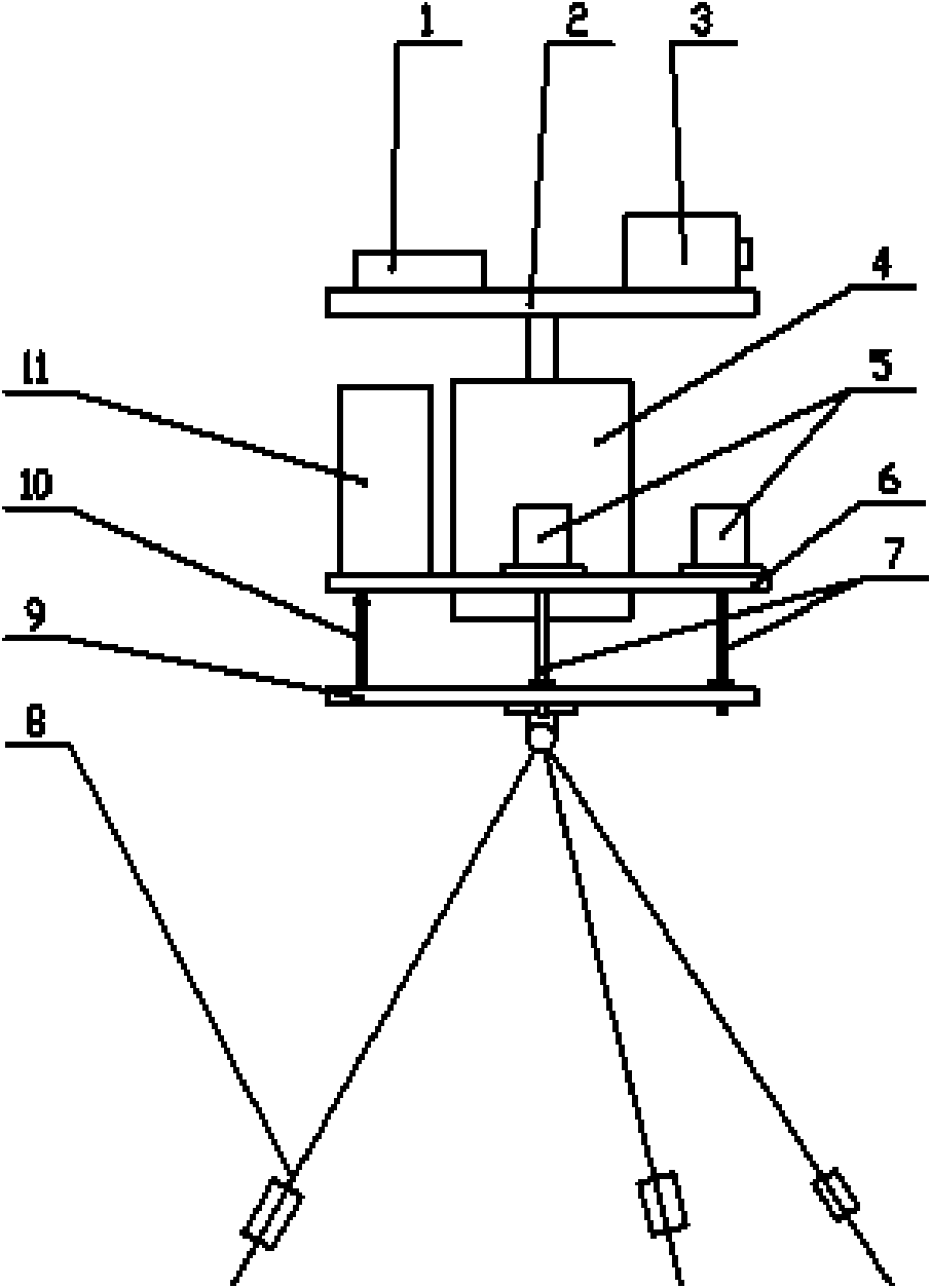
[0033] Such as figure 1 As shown, the entire base station is fixed on a height-adjustable tripod 8, the laser transmitter 3 is installed on the horizontal rotary platform 2, and a horizontal detection module 1 is also installed on the horizontal rotary platform 2, and the horizontal rotary platform 2 passes through the horizontal rotary motor 4 Driven to rotate back and forth on the horizontal plane, the motor comes with a horizontal rotation angle measurement module, the horizontal rotation motor 4, the horizontal adjustment motor 5 are fixedly connected to the support circular plate 6, the support circular plate 6 and the base 9 are connected by ...


PUM


Abstract

The invention discloses a laser three-point dynamic positioning method and a system thereof. The method comprises: two base stations which are a first base station and a second base station are arranged at the fixed positions; a main station is arranged on a moving object; the base stations transmit the laser to the main station; the base stations are connected with the main station by wireless communication; a base line is defined to be a connecting line between the first station and the second station; the first base station acquires the included angle alpha between the main station corresponding to the first base station and the base line, and the included angle beta between the main station corresponding to the second base station and the base line; the first and the second base stations respectively send the included angles alpha and beta to the main station; and the main station can determine the position of the main station according to the included angles alpha and beta as wellas the length L of the base line. The laser three-point dynamic positioning system is constructed according to the method. The technology can be used for locating the moving object in field operationin the environment without marks in a dynamic, and has the advantages of high locating accuracy, simple operation principle and low implementation cost.

Description

technical field [0001] The invention belongs to the technical field of automatic positioning, and relates to a laser three-point dynamic positioning method and system. Background technique [0002] Automatic positioning technology is a combination of electronic information technology, computer technology, control technology and other disciplines. It is more and more widely used in modern industrial and agricultural production, such as plowing, planting, sowing, harvesting, drug spraying and weeding in precision agriculture. , information collection, generation of variable output maps and variable input operations, land leveling in the industrial and agricultural construction industry, automatic vehicle walking, etc., all need to apply automatic positioning technology. [0003] At present, the widely used positioning systems include global positioning system, radio positioning, visual positioning, inertial sensor positioning, etc. Generally speaking, the high-precision GPS p...

Claims


Application Information

Patent Timeline
Patent Type & Authority Applications(China)
IPC IPC(8): G01S5/16G01C21/12
Inventor 蒋蘋罗亚辉王奕胡文武艾卫中谢昌盛谢艳群
Owner HUNAN AGRICULTURAL UNIV
Learn More