Expandable underactuated cable-rod truss type mechanical claw

A robotic gripper and truss-type technology, which is applied in the field of modular robotic grippers, can solve the problems of poor shape adaptability of target objects, difficult expansion of SARAH grippers, and heavy weight of SARAH grippers, and achieve strong target adaptability and mature processing technology , the effect of rich material resources

Active Publication Date: 2014-05-14
HARBIN INST OF TECH
View PDF4 Cites 29 Cited by
  • Summary
  • Abstract
  • Description
  • Claims
  • Application Information

AI Technical Summary

Problems solved by technology

[0006] The present invention aims to solve the problems of traditional underactuated mechanism and SARAH claws, such as heavy weight, complex structure, poor adaptability to

Method used


Image

  • Expandable underactuated cable-rod truss type mechanical claw
  • Expandable underactuated cable-rod truss type mechanical claw
  • Expandable underactuated cable-rod truss type mechanical claw

Examples


specific Embodiment approach 1

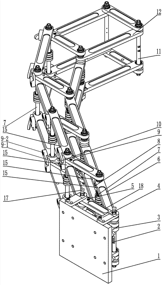
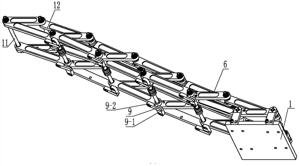
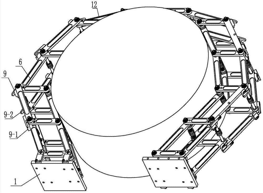
[0019] Specific implementation mode one: combine Figure 1-Figure 4 Explain that an expandable underactuated cable-bar truss-type robotic gripper in this embodiment includes a front-end connection device, an inter-bar rotation angle limiting mechanism 9, an end cable-bar truss 12, ropes, multiple positioning columns 10, and multiple expandable modules. Cable-strut truss 6;

[0020] The front connecting device comprises a connecting plate 1, two rope shafts 2, two spacer posts 5, two mounting plates 4, two transition plates 18 and four supporting plates 3, and one end surface of the connecting plate 1 is equipped with four A support plate 3, four support plates 3 are arranged in a rectangular array, two support plates 3 on the same side in the vertical direction are provided with rope shafts 2, and two mounting plates 4 are installed on the upper surface of the connecting plate 1, A motor 17 is fixedly installed on each mounting plate 4, and the output shaft of the motor 17 is...

specific Embodiment approach 2

[0029] Specific implementation mode two: combination figure 1 To illustrate, the frictional damping metal sheet 8 in this embodiment is a steel sheet. Such a setting is cheap and easy to obtain, and changing the pressure at both ends of the frictional damping can change the resistance torque between the two rods, thereby realizing the controllable design of the underactuated mechanism. Others are the same as in the first embodiment.

specific Embodiment approach 3

[0030] Specific implementation mode three: combination figure 1 To illustrate, the frictional damping metal sheet 8 in this embodiment is an aluminum sheet. Such a setting is cheap and easy to obtain, and changing the pressure at both ends of the frictional damping can change the resistance torque between the two rods, thereby realizing the controllable design of the underactuated mechanism. Others are the same as in the first embodiment.


PUM


Abstract

The invention relates to a modularized mechanical claw can be used for grabbing objects in different shapes in space, in particular to an expandable underactuated cable-rod truss type mechanical claw to solve the problems that a traditional underactuated mechanism and an SARAH claw are heavy in weight, complex in structure, poor in capacity of adaptive to shapes of the objects to be grabbed and small in grabbing force, and the SARAH claw is difficult to expand. The expandable underactuated cable-rod truss type mechanical claw comprises a front end connecting device, a corner limiting mechanism among rods, a tail end cable-rod truss, a rope, a plurality of positioning posts and a plurality of expandable modularized cable-rod trusses. The front end connecting device comprises a connecting plate, two rope shafts, two limited posts, two installing plates, two transition plates and four supporting plates, the rope shafts penetrate through the two supporting plates located on the same side in the vertical direction, and an output shaft of a motor is arranged vertically and connected with the corresponding rope shaft; each expandable modularized cable-rod truss comprises two rope winding shafts, two frictional damping metal pieces and six connecting rods. The invention belongs to the field of space robots.

Description

technical field [0001] The invention relates to a modular manipulator gripper which can be used for grabbing objects of different shapes in space, and belongs to the technical field of space robots. Background technique [0002] With the increase of human space activities and the needs of deep space exploration missions, space robots are playing an increasingly important role. For example, the application of multi-degree-of-freedom space manipulators can carry out tasks such as space cargo handling, space assembly, and on-orbit maintenance. The application of robot astronauts can replace astronauts to engage in extravehicular operations, and the application of planetary detection robots can conduct unmanned exploration of the planet. Although the current space robot has the advantages of high intelligence and strong adaptability to tasks, its structure is relatively complex. Generally, each joint is an active drive joint, resulting in a large number of motors, heavy weight, ...

Claims


Application Information

Patent Timeline
IPC IPC(8): B25J15/08
Inventor 刘荣强郭宏伟吴楠邓宗全
Owner HARBIN INST OF TECH
Why Eureka
Try Eureka