Prefabricated concrete column and steel beam joint

A concrete column, prefabricated assembly technology, applied in the direction of architecture, building structure, etc., can solve the problems of large volume, difficult assembly, etc., achieve the effects of strong ductility and deformation recovery ability, reduce the connection of steel joints, and simplify the structure of the joint area

Pending Publication Date: 2017-08-22
CHONGQING UNIV
View PDF5 Cites 9 Cited by
  • Summary
  • Abstract
  • Description
  • Claims
  • Application Information

AI Technical Summary

Problems solved by technology

In this device, at the beam-column joints, although the steel column hoop has a restraining effect on the internal reinforced concrete, it can improve the bending and shear bearing capacity of the joint column section to a certain extent, but the concrete column in this device is a As a whole, the volume is larger and the assembly is more difficult

Method used


Image

  • Prefabricated concrete column and steel beam joint
  • Prefabricated concrete column and steel beam joint
  • Prefabricated concrete column and steel beam joint

Examples


Embodiment 1

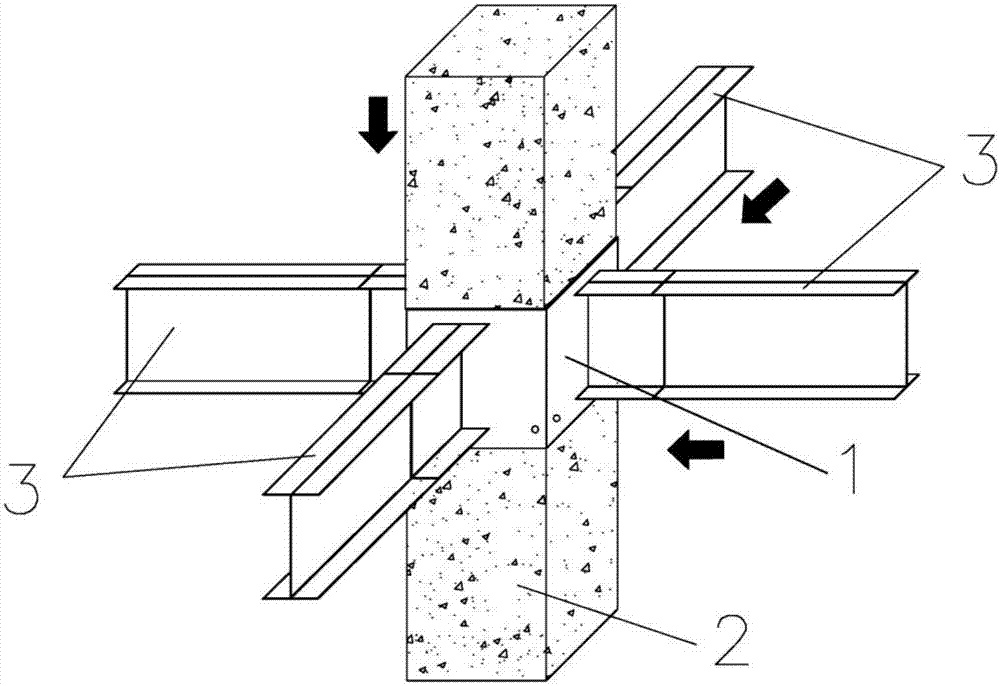
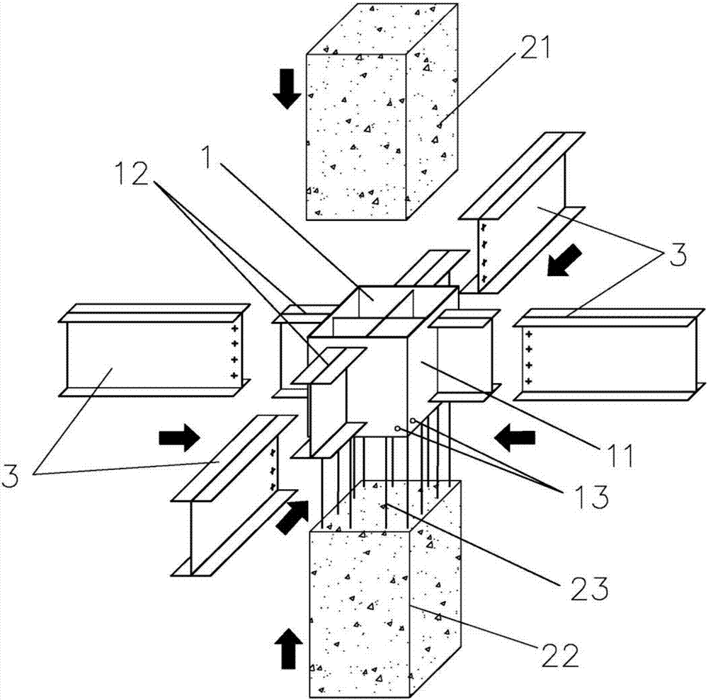
[0032] Such as figure 1 and figure 2 As shown, a prefabricated concrete column-steel beam node includes a prefabricated node unit 1, a prefabricated concrete column 2 and a prefabricated steel beam 3, the prefabricated concrete column 2 includes an upper column 21 and a lower column 22, and the prefabricated node The unit 1 includes a box body 11 and a short steel beam 12. The short steel beam 12 includes a cross end inside the box body that is connected as a cross and an extended end that penetrates and extends out of the box body. The extended end is connected to the box body. The prefabricated steel beams 3 are connected, the lower part of the box body 11 is provided with a grouting hole 13, the prefabricated node unit 1 is connected between the upper column 21 and the lower column 22, and the prefabricated node unit 1 is connected to the upper column 21, The lower columns 22 are connected by grouting.

[0033] In this embodiment: vertical longitudinal ribs 23 are reserv...

Embodiment 2

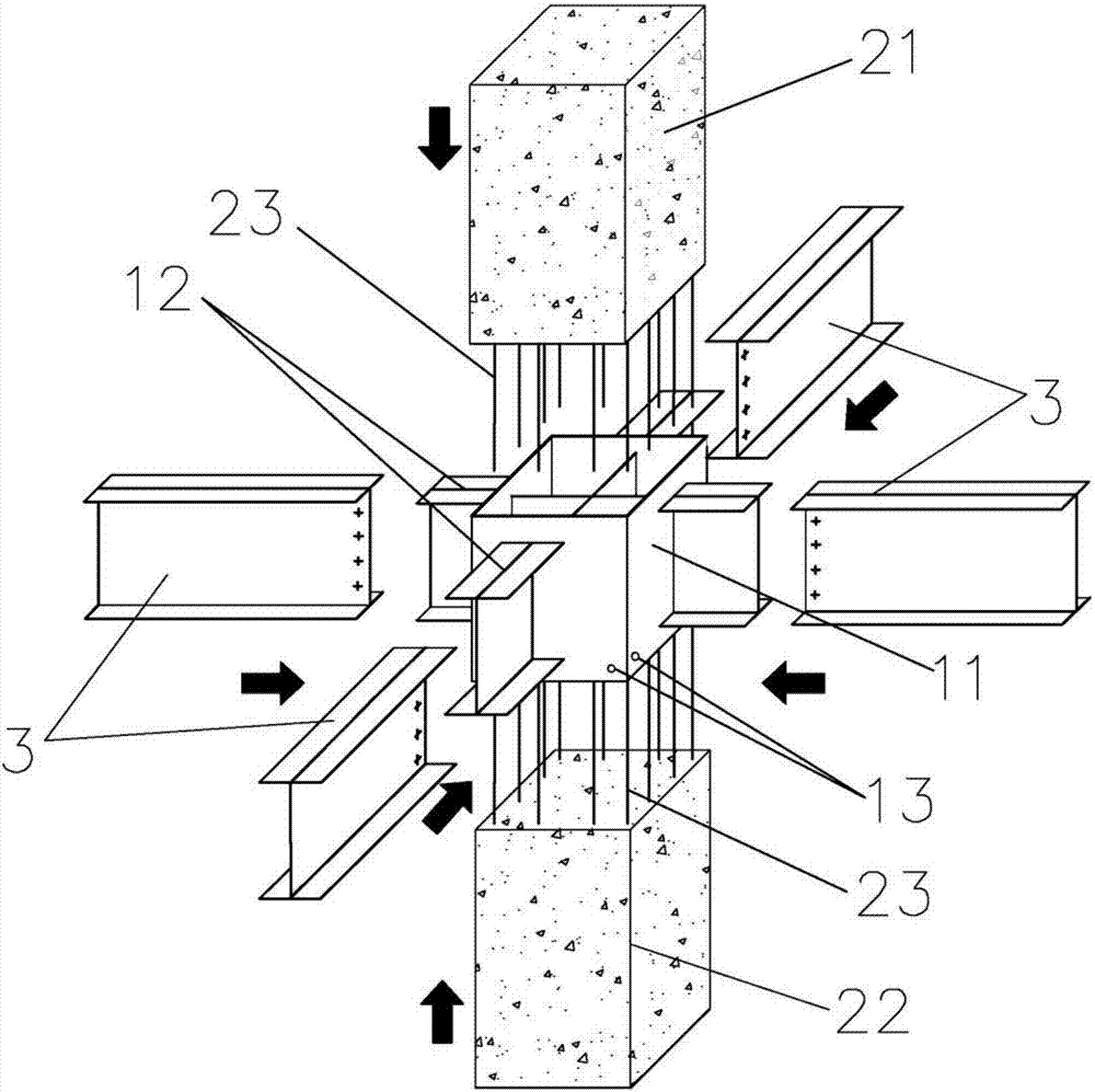
[0038] Such as image 3 As shown, the difference between Embodiment 2 and Embodiment 1 is that: the top of the lower column 22 and the bottom of the upper column 21 are reserved vertical longitudinal ribs 23, and they are overlapped in the prefabricated node unit 1, And connected into a whole by grouting.


PUM


Abstract

The invention discloses a prefabricated concrete column and steel beam joint. The joint comprises a prefabricated joint unit, a prefabricated concrete column and a prefabricated steel beam. The prefabricated concrete column comprises an upper column body and a lower column body, the prefabricated joint unit comprises a box body and a short steel beam, the short steel beam comprises a cross-shaped end and an extending end, the cross-shaped end is located in the box body and is in cross connection, the extending end penetrates out of the box body, and the extending end is connected with the prefabricated steel beam; the lower portion of the box body is provided with a grouting hole, the prefabricated joint unit is arranged between the upper column body and the lower column body, and the prefabricated joint unit is connected between the upper column body and the lower column body through grouting. According to the prefabricated concrete column and the steel beam joint, a prefabricated part is divided into the prefabricated concrete column, the prefabricated steel beam and the prefabricated joint unit, all the parts can be prefabricated in a prefabricating factory, the construction progress can be accelerated, and the construction quality can be improved; in addition, the size of the divided prefabricated part becomes small, and the problems that an existing prefabricated part is large in size and difficult to transport and assemble are solved.

Description

technical field [0001] The invention relates to a concrete column-steel beam joint, in particular to a prefabricated assembled concrete column-steel beam joint. Background technique [0002] With the continuous development of the structural forms of high-rise buildings, more and more new hybrid structural systems have emerged. The reinforced concrete column-steel beam composite structural system (RCS composite structural system for short) combines steel structures and The double advantage of concrete structure is called "low cost and high efficiency" structure form. Compared with steel structure, it has the characteristics of saving steel and increasing the rigidity of the building. Compared with the structure, it has the characteristics of reducing the cross-sectional size of the member, increasing the span of the structure, and increasing the ductility of the structure, so it has received extensive attention from many scholars. In order to ensure reliable force transmissi...

Claims


Application Information

Patent Timeline
Patent Type & Authority Applications(China)
IPC IPC(8): E04B1/30E04B1/58
CPCE04B1/185E04B1/30
Inventor 刘立平郑歆耀
Owner CHONGQING UNIV
Why Eureka
Try Eureka