Steel wire balancer and special trolley provided with lifting arm support

A technology of balancer and wire rope, which is applied in the direction of cranes, etc., can solve the problem of large space occupied by balancing equipment, and achieve the effect of solving force and prolonging the service life

Active Publication Date: 2014-05-14
XCMG CONSTR MACHINERY
View PDF6 Cites 1 Cited by
  • Summary
  • Abstract
  • Description
  • Claims
  • Application Information

AI Technical Summary

Problems solved by technology

[0008] The purpose of the present invention is to propose a wire rope balancer with a small footprint and a special veh

Method used


Image

  • Steel wire balancer and special trolley provided with lifting arm support
  • Steel wire balancer and special trolley provided with lifting arm support
  • Steel wire balancer and special trolley provided with lifting arm support

Examples


Embodiment Construction

[0031] The technical solutions of the present invention will be described in further detail below with reference to the accompanying drawings and embodiments.

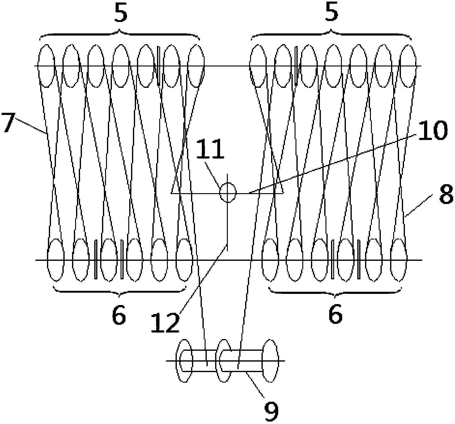
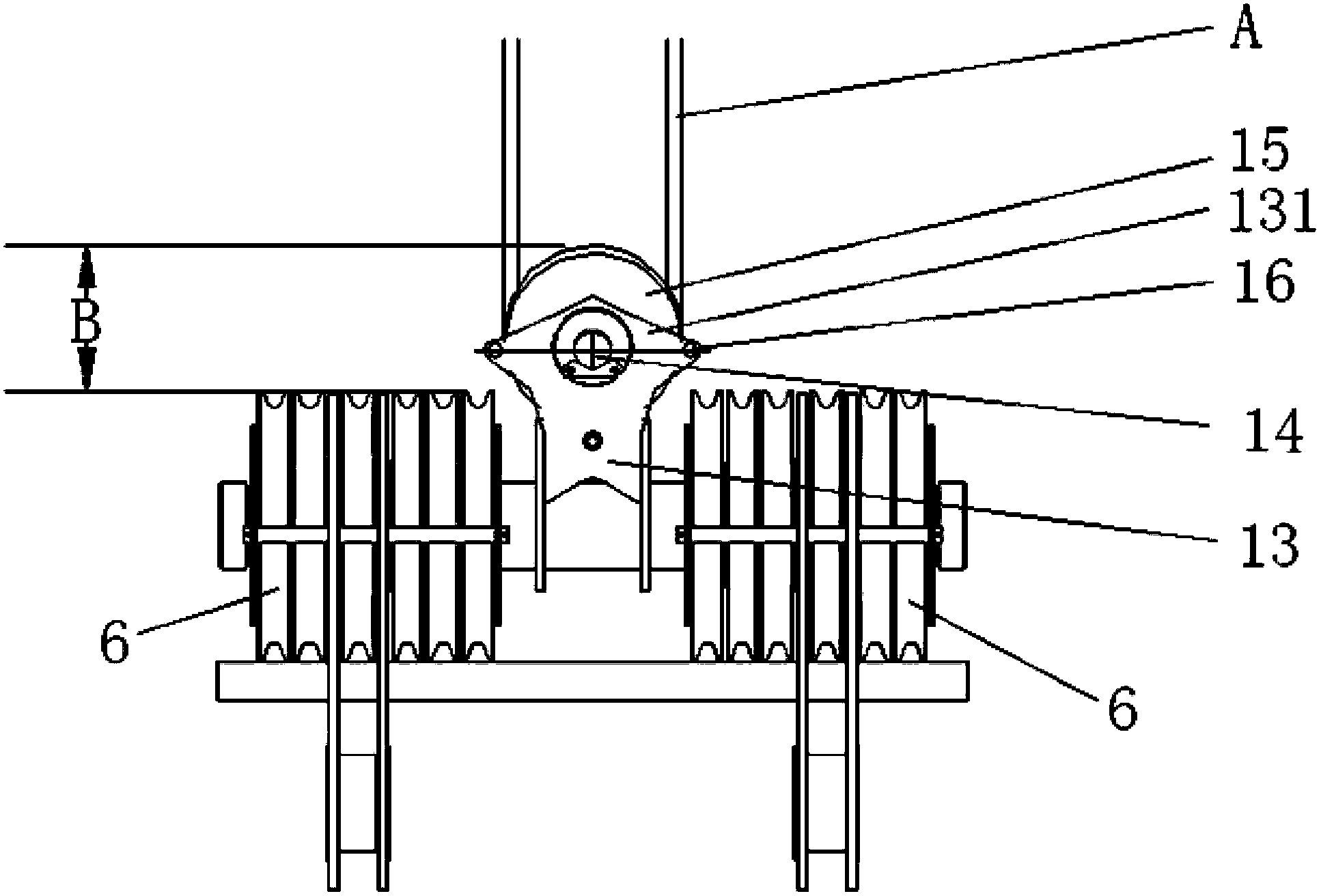
[0032] image 3 A schematic diagram of the connection relationship between the wire rope balancer and the lower mast pulley block provided by the present invention; Figure 4 It is a schematic diagram of the connection relationship between the wire rope balancer, the mast pulley block and the luffing hoist provided by the present invention. Such as image 3 , Figure 4As shown, the present invention is in order to be able to balance and adjust the connection between the first steel wire rope 7 wound on the left mast pulley block and the second steel wire rope 8 wound on the right mast pulley block in a small space. The difference in length is to solve the problem that the balance equipment occupies a large space in the prior art.

[0033] The wire rope balancer provided by the present invention includes a bracket 1...


PUM

PropertyMeasurementUnit
Angleaaaaaaaaaa

Abstract

The invention relates to a steel wire balancer and a special trolley provided with a lifting arm support. The steel wire balancer is used for balancing the length difference of steel wires wound on mast pulley blocks positioned on a left side and a right side, and the steel wire balancer comprises a support frame and a balance wheel, wherein the bottom of the support frame is fixed; the central hole of the balance wheel is connected to the support frame through a shaft; the axial line direction of the balance wheel is perpendicular to the mast pulley blocks; the side wall of the balance wheel is provided with an inner groove in a circle; and one end of one steel wire is fixed on a winding drum with variable amplitude winding, and the other end of the steel wire is wound on the mast pulley block positioned on one of the left side and the right side, then wound in the inner groove positioned on the lower middle part of the balance wheel and then wound on the mast pulley block positioned on the other one of the left side and the right side to be fixed on the winding drum with variable amplitude winding. The steel wire balancer disclosed by the invention has the advantages of small occupied space and limitless regulating quantity.

Description

technical field [0001] The invention relates to the field of engineering machinery, in particular to a wire rope balancer and a special vehicle equipped with a lifting arm frame. Background technique [0002] At present, my country and other countries in the world are vigorously developing the construction of petrochemical, wind power, high-speed rail and other large-scale projects. The large crawler crane is a device that uses a jib structure to lift heavy objects, and as an essential equipment for the safe construction of large-scale projects, it plays an important role in the construction process of the project. [0003] figure 1 Shown is a side view of the entire vehicle of the crawler crane. Such as figure 1 As shown, the crawler crane includes a main engine 1, a boom 2 pinned to the main engine 1, and a luffing mast 3, wherein a pull plate is pinned between the upper end of the jib 2 and the first end of the luffing mast 3 4. The second end of the luffing mast 3 is...

Claims


Application Information

Patent Timeline
IPC IPC(8): B66C23/72B66C23/36
Inventor 刘玉泉姜锡祥张自永
Owner XCMG CONSTR MACHINERY
Why Eureka
Try Eureka