Piston pump

A technology of piston pump and pump piston, applied in the direction of pump, multi-cylinder pump, pump element, etc., to achieve the effect of high cost saving, high reliability and low friction

Inactive Publication Date: 2014-05-14
ROBERT BOSCH GMBH
View PDF6 Cites 5 Cited by
  • Summary
  • Abstract
  • Description
  • Claims
  • Application Information

AI Technical Summary

Problems solved by technology

[0003] A disadvantage of the prior art is that in such piston pumps a correspondingly large installation chamber for the piston pump is required due to the arrangement of the two components at right angles to one another

Method used


Image

  • Piston pump
  • Piston pump
  • Piston pump

Examples


Embodiment Construction

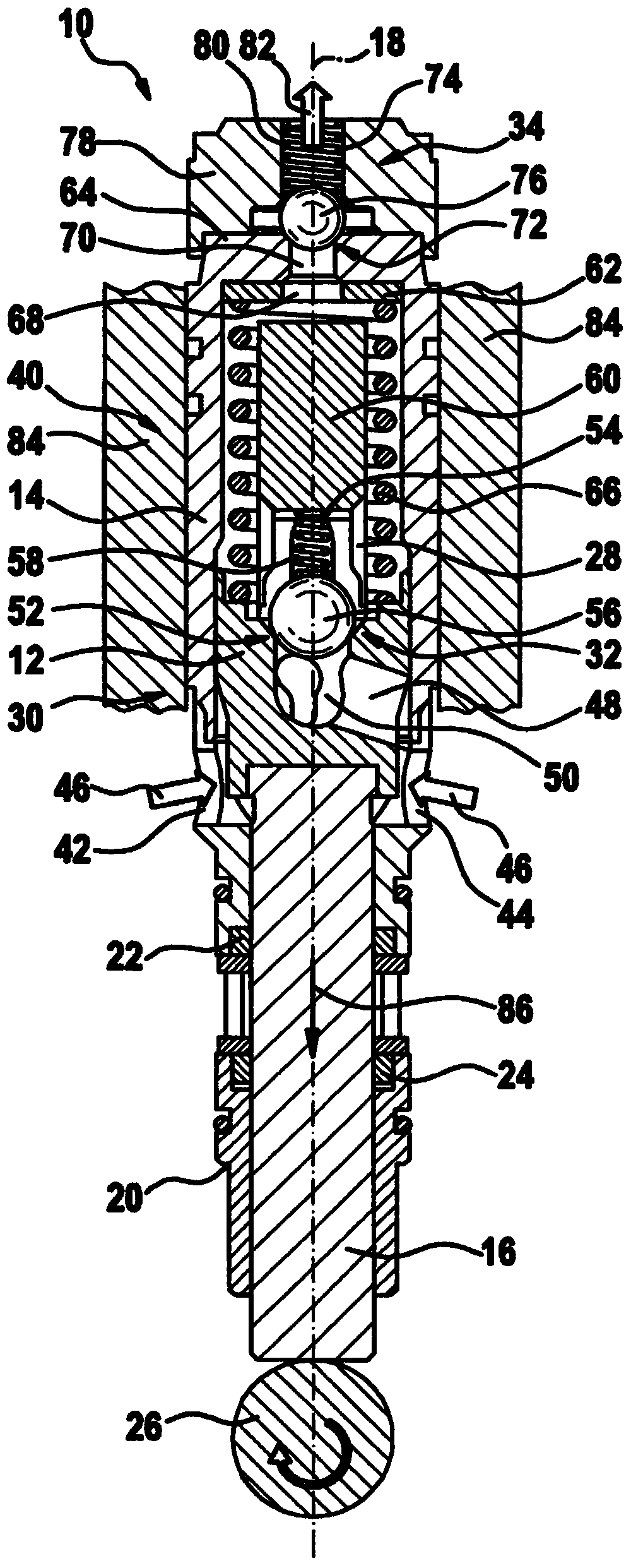
[0037] figure 1 A piston pump 10 according to one embodiment is shown with a pressure generating device 30 and a control device 40 . The piston pump 10 illustratively comprises a pump piston 12 , preferably made of a suitable elastic thermoplastic and / or thermosetting plastic material, which is oscillatably movable in a cylinder 14 along a longitudinal axis 18 by means of a piston rod 16 , exist figure 1 where are illustratively upward and downward motions. The piston rod 16 is received axially displaceably in an essentially hollow-cylindrical guide bush 20 and is sealed relative thereto by sealing rings 22 , 24 . The piston rod 16 is driven by means of a schematically shown eccentric drive 26 , so that the pump piston 12 is moved along the longitudinal axis 18 in the cylinder 14 in a desired oscillating upward and downward motion. However, it should be pointed out that a suitable eccentric drive is sufficiently known to a person skilled in the art and is not the subject of...


PUM


Abstract

The present invention relates to a piston pump (10) form high-pressure transmission of a fluid to be transmitted. The piston pump (10) comprises a pressure generating unit (30) and a control unit (40) which are arranged together in an individual housing (84) and aligned to each other along a common longitudinal axis (18).

Description

technical field [0001] The invention relates to a piston pump for high-pressure conveyance of a fluid to be conveyed, which has a pressure generating device and a control device. Background technique [0002] Such piston pumps are known from the prior art and are used, for example, in high-pressure cleaners. The piston pump comprises two components in the form of a pressure generating part and a control group part, which are arranged structurally separate from one another. The first assembly basically consists of a piston rod with a pump piston, a guide bush, a pressure spring with a spring disk and a sealing element, while the second assembly combines the inlet and outlet valves and other electromechanical control elements, especially with For switching on and off the associated drive motor. The two components are connected to one another via a compression chamber and are positioned, for example, at right angles to one another, wherein the drive of the piston rod and the ...

Claims


Application Information

Patent Timeline
Patent Type & Authority Applications(China)
IPC IPC(8): F04B53/16F04B53/14F04B53/10
CPCF04B53/126B08B3/026B08B2203/027F04B1/0408F04B1/0421F04B1/0452F04B1/053
Inventor S·克恩
Owner ROBERT BOSCH GMBH
Why Eureka
Try Eureka