Three-conical-face synchronizer with lubricating oil way

A lubricating oil circuit and synchronizer technology, which is applied in the direction of engine lubrication, clutches, couplings, etc., can solve the problems of accelerating the early wear and failure of three-cone synchronizers, increasing manufacturing costs, and long shifting time. The driver's operation is comfortable and light, the service life is improved, and the shifting time is short.

Active Publication Date: 2014-05-14
SHAANXI FAST AUTO DRIVE GROUP CO LTD
View PDF8 Cites 17 Cited by
  • Summary
  • Abstract
  • Description
  • Claims
  • Application Information

AI Technical Summary

Problems solved by technology

[0002] Current double cone lock ring synchronizers (see figure 1 ) is widely used, but in some transmissions with relatively large shift ratios, the double-cone lock-ring synchronizer has the problems of long shift time and large shift force. The structure of the three-cone synchronizer Similar to the double-cone lock-ring synchronizer, the manufacturing cost is slightly increased, and the triple-cone synchronizer has better synchronization performance and shifting convenience than the double-cone lock-ring synchronizer
The three-cone synchronizer will generate a lot of heat during synchronization due to the many friction cones. The concentration of heat will cause the ablation of the synchronous ring, reduce the wear resistance of the friction material, and accelerate the early wear of the three-cone synchronizer. and failure

Method used


Image

  • Three-conical-face synchronizer with lubricating oil way
  • Three-conical-face synchronizer with lubricating oil way
  • Three-conical-face synchronizer with lubricating oil way

Examples


Embodiment Construction

[0022] The present invention will be described in further detail below in conjunction with the accompanying drawings.

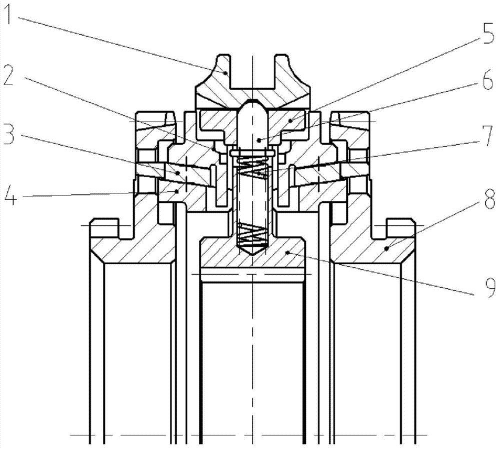
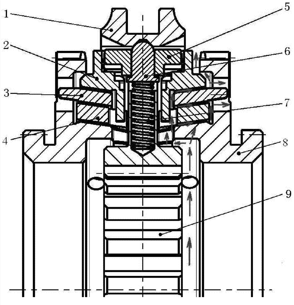
[0023] see Figure 2-5 , a three-cone synchronizer with a lubricating oil passage in the present invention, including a sliding tooth sleeve 1, a pair of outer friction rings 2, a pair of friction intermediate rings 3, a pair of inner friction rings 4, a slider 5, a pin 6, Spring 7, a pair of combined ring gear 8 and gear hub 9;

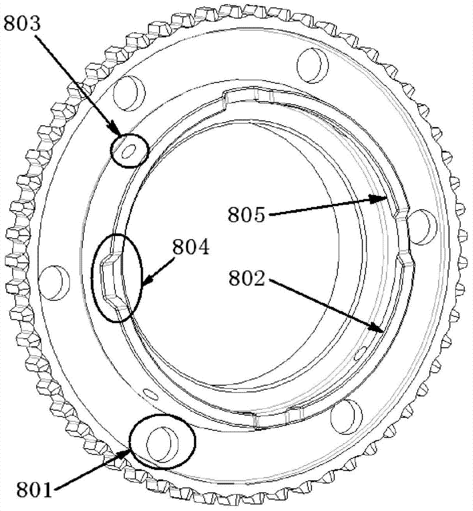
[0024] Among them, the inner ring of the outer friction ring 2 is provided with 6 first claws 201 in the circumferential direction, and the inner friction ring 4 is provided with 6 oil passage grooves 401 matching with the 6 first claws 201 in the circumferential direction. There are 6 oil holes 801 arranged in the circumferential direction, and a conical body 802 is arranged on the end surface, and 4 oil holes 803 and 4 radial oil grooves 804 are arranged in the circumferential direction of the conical body 802, and the radial oil...


PUM


Abstract

The invention discloses a three-conical-face synchronizer with a lubricating oil way. The three-conical-face synchronizer comprises a sliding gear sleeve, external friction rings, middle friction rings, internal friction rings, a sliding block, a pin, a spring, combined gear rings and a gear hub. A pair of the combined gear rings are symmetrically arranged on the two sides of the gear hub, and conical face bodies of the combined gear rings face one side of the gear hub. A pair of the internal friction rings are arranged on the combined gear rings and provided with a pair of the middle friction rings. Second claws of the middle friction rings extend into oil passing holes of the combined gear rings. A pair of the external friction rings are arranged on the middle friction rings. First claws of the external friction rings extend into oil passing grooves of the internal friction rings. The sliding gear sleeve, the sliding block, the pin and the spring are arranged between the external friction rings. One end of the pin penetrates through the sliding block and is matched with the sliding gear sleeve, and the other end of the pin makes contact with the gear hub through the spring. Compared with a double-conical-face synchronizer, the three-conical-face synchronizer is shorter in shift time, smaller in shift force, more comfortable to control and longer in service life.

Description

【Technical field】 [0001] The invention belongs to the field of automobile transmission devices, and in particular relates to a three-cone synchronizer with lubricating oil passages. 【Background technique】 [0002] Current double cone lock ring synchronizers (see figure 1 ) is widely used, but in some transmissions with relatively large shift ratios, the double-cone lock-ring synchronizer has the problems of long shift time and large shift force. The structure of the three-cone synchronizer Similar to the double-cone lock-ring synchronizer, the manufacturing cost is slightly increased, and the triple-cone synchronizer has better synchronization performance and shifting convenience than the double-cone lock-ring synchronizer. The three-cone synchronizer will generate a lot of heat during synchronization due to the many friction cones. The concentration of heat will cause the ablation of the synchronous ring, reduce the wear resistance of the friction material, and accelerate ...

Claims


Application Information

Patent Timeline
Patent Type & Authority Applications(China)
IPC IPC(8): F16D23/02F16N1/00
CPCF16D2300/06F16D23/025
Inventor 魏小强郭增钢张发勇
Owner SHAANXI FAST AUTO DRIVE GROUP CO LTD
Why Eureka
Try Eureka