
Light-emitting module and illuminating apparatus and lamp box including light-emitting module

A technology for light-emitting modules and lighting devices, which is applied to lighting devices, components of lighting devices, lighting and heating equipment, etc., and can solve problems such as shadow areas.

Active Publication Date: 2014-05-14
OPTOTRONIC GMBH
View PDF6 Cites 1 Cited by
  • Summary
  • Abstract
  • Description
  • Claims
  • Application Information

AI Technical Summary

Problems solved by technology

However, this unified design will cause each light-emitting module to irradiate uniformly only in the direction along the optical axis, but there will be dark areas on the mounting surface where the light-emitting modules are located, especially between two adjacent light-emitting modules. A shaded area will appear in the middle area
This situation can limit the lighting effects affecting the entire lighting installation

Method used


Image

  • Light-emitting module and illuminating apparatus and lamp box including light-emitting module
  • Light-emitting module and illuminating apparatus and lamp box including light-emitting module
  • Light-emitting module and illuminating apparatus and lamp box including light-emitting module

Examples


Embodiment Construction

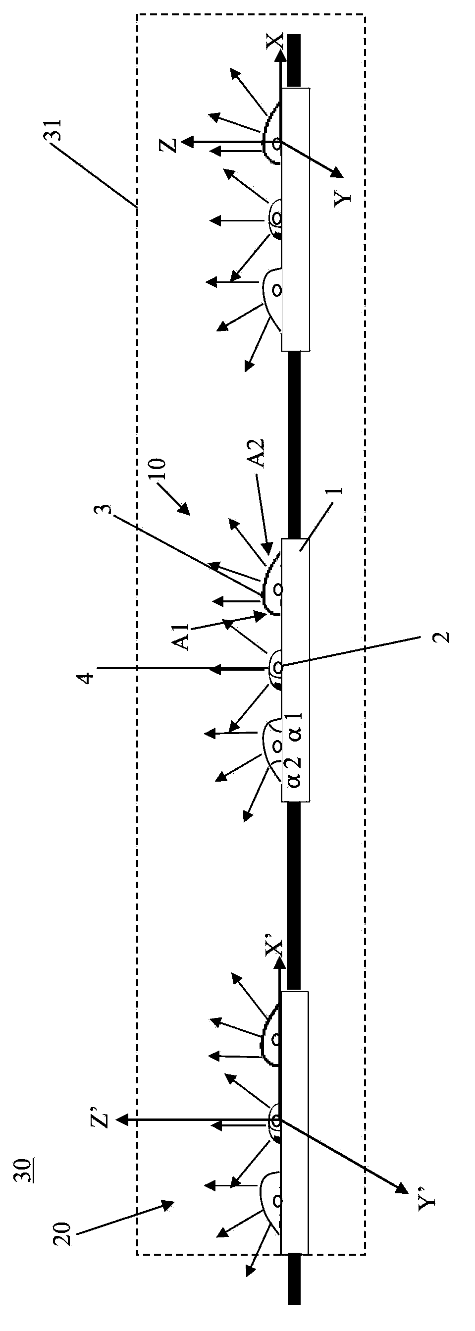
[0026] In the following detailed description, reference is made to the accompanying drawings which form a part hereof, and in which are shown by way of illustrations specific embodiments in which the invention may be practiced. With respect to the figures, directional terms such as "top", "bottom", "inner", "outer", etc. are used with reference to the orientation of the figures being described. Since components of embodiments of the present invention may be placed in many different orientations, the terminology of orientation is used for illustration only and not in any limiting sense. It is to be understood that other embodiments may be utilized and structural or logical changes may be made without departing from the scope of the present invention. Therefore, the following detailed description should not be taken in a limiting sense, and the invention is defined by the appended claims.

[0027] It should be understood that, unless otherwise specified, features of different e...


PUM


Abstract

The invention relates to a light-emitting module (10) which comprises a circuit board (1) provided with an edge region and a central region, at least one first light source arranged in the edge region of one plane of the circuit board (1) and at least one first optical device (3) matched with the corresponding first light source. The light-emitting module (10) is characterized in that light beams emitted by each first optical device (3) towards a lateral external space outside the edge region of the circuit board (1) are more than light beams emitted by the same first optical device (3) towards the central region of the circuit board (1). In addition, the invention further relates to an illuminating apparatus and a lamp box including the light-emitting module.

Description

technical field [0001] The invention relates to a light emitting module, an illuminating device and a light box including the light emitting module. Background technique [0002] LED lighting modules have the advantages of energy saving and high efficiency, so they occupy a dominant position in today's lighting field. With the development of lighting technology, retrofit lamps using LEDs as light sources have gradually replaced fluorescent lamps and are widely used in various occasions. For example, in the advertising industry, it is necessary to install multiple LED light-emitting modules in an electronic billboard or display lamp in a linear arrangement to achieve a predetermined lighting pattern, where it is inevitable between two adjacent light-emitting modules with a certain spacing. [0003] In the prior art, the same lens is often installed on each light source of the light emitting module, thereby improving lighting efficiency. However, this unified design will ca...

Claims


Application Information

Patent Timeline
Patent Type & Authority Applications(China)
IPC IPC(8): F21S2/00F21V5/04F21V5/08F21V19/00F21Y101/02
CPCF21Y2103/10F21Y2113/00F21Y2113/20F21Y2115/10H01L25/0753H01L33/58
Inventor 明玉生何源源冯耀军欧智君
Owner OPTOTRONIC GMBH
Features
  • Generate Ideas
  • Intellectual Property
  • Life Sciences
  • Materials
  • Tech Scout
  • Unparalleled Data Quality
  • Higher Quality Content
  • 60% Fewer Hallucinations
Learn More