Check patentability & draft patents in minutes with Patsnap Eureka AI!

Refrigeration cycle device

A refrigeration cycle and circulating flow path technology, applied in refrigerators, refrigeration components, refrigeration and liquefaction, etc., can solve the problems of high temperature of ejected gas, inability to ensure long-term reliability, easy aging of oil, etc. The effect of long-term reliability

Active Publication Date: 2014-05-14
HITACHI JOHNSON CONTROLS AIR CONDITIONING INC
View PDF7 Cites 2 Cited by
  • Summary
  • Abstract
  • Description
  • Claims
  • Application Information

AI Technical Summary

Problems solved by technology

[0009] However, a refrigerant compressor using R32 has a higher discharge gas temperature than a refrigerant compressor using R410A etc.
[0010] Therefore, compared with refrigerant compressors using R410A, etc., the refrigerant compressors using R32 have resin parts and oil that are more likely to deteriorate, and there is a problem that long-term reliability cannot be ensured.
[0011] In addition, when the temperature of the discharged gas rises, the amount of R32 dissolved in the oil (refrigerant dissolved amount) decreases, so the refrigerant compressor using R32 also has the problem of a decrease in the pressure of the back pressure chamber.

Method used


Image

  • Refrigeration cycle device
  • Refrigeration cycle device
  • Refrigeration cycle device

Examples


Embodiment Construction

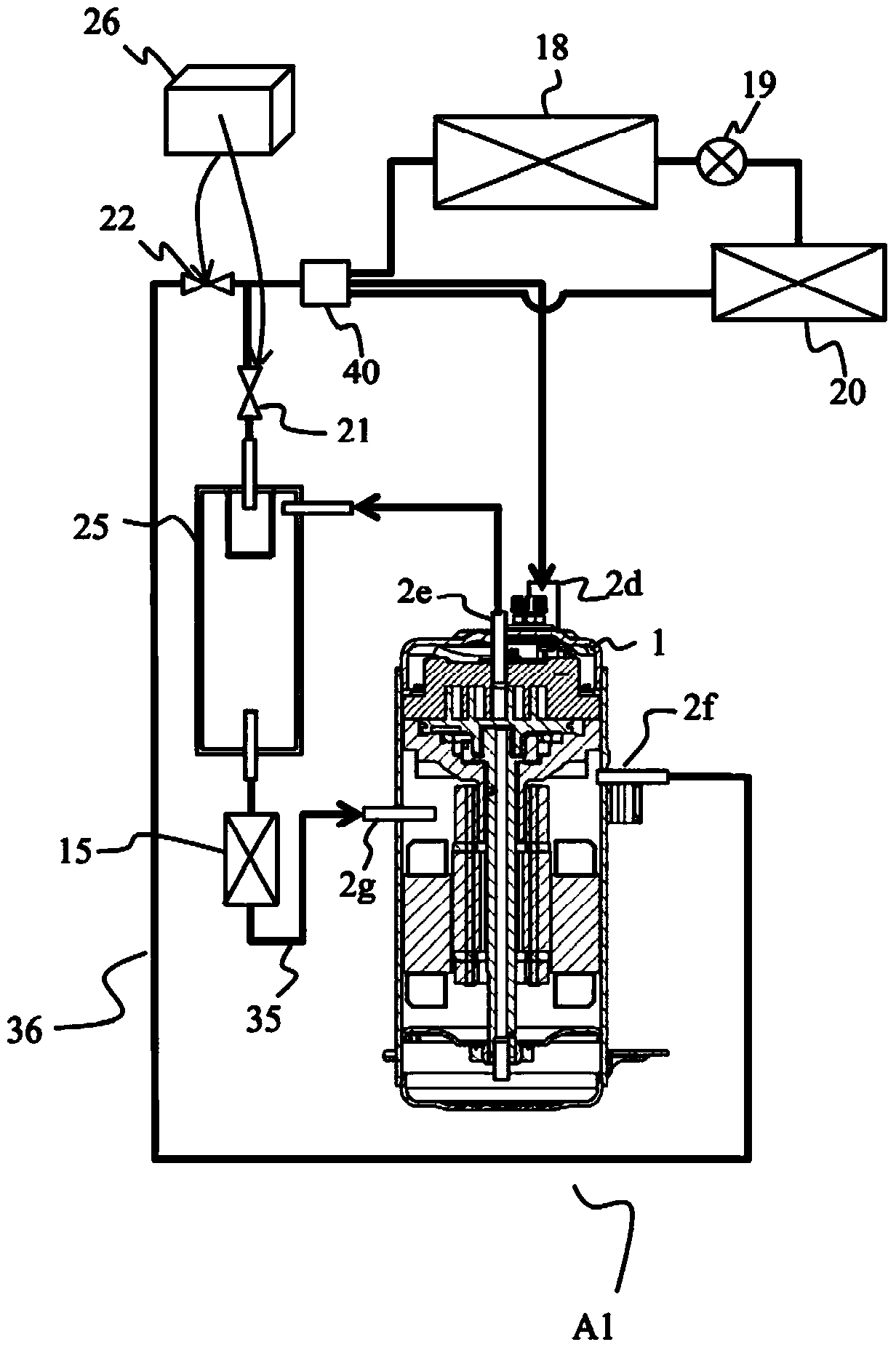
[0065] The main feature of the refrigeration cycle device of this embodiment is that the discharged gas and oil, or only the oil is cooled by a cooler and returned to the compressor to lower the temperature of the compressor. The refrigeration cycle device of this embodiment can be applied to refrigerators, refrigerators, heat pump water heaters, air conditioners, and the like. Hereinafter, assuming that this refrigeration cycle device is applied to an air conditioner, the present embodiment will be described with reference to the drawings as appropriate.

[0066] figure 1 It is a configuration explanatory diagram of the refrigeration cycle apparatus according to the present embodiment. like figure 1 As shown, the refrigeration cycle device A1 according to this embodiment is sequentially connected with a compressor 1, an oil separator 25, a first on-off valve 21, an outdoor heat exchanger 18, a decompression device 19 (expansion valve), and an indoor heat exchanger. The dev...


PUM


Abstract

The aim of the invention is that a refrigeration cycle device using R32 helps to ensure long-term reliability and maintaining of pressure of a back press chamber, and enables the capability of a condenser to be improved. The refrigeration cycle device comprises a cycle flow path, a first bypass flow path, a cooler, a second bypass flow path, a second open and close valve, and a control mechanism. A compressor, an oil separation device, a first open and close valve, a condenser, a pressure reducing device and an evaporator are connected in order by pipes to form the cycle flow path for cycling of R32 serving as a refrigerant. The first bypass flow path enables the oil separation device and the compressor to be connected by a pipe. The cooler is arranged on the first bypass flow path. The second bypass flow path enables the compressor and the condenser to be connected via a pipe. The second open and close valve is arranged on the second bypass flow path. The control mechanism opens one of the first open and close valve and the second open and close valve and closes the other one.

Description

technical field [0001] The invention relates to a refrigeration cycle device. Background technique [0002] Difluoromethane (hereinafter referred to as "R32") has zero ozone destruction coefficient, and the global warming coefficient of R32 is about 1 / 3 of that of R410A. Therefore, by using R32 instead of R410A widely used in refrigeration cycle devices at present, it is possible to contribute to the reduction of environmental load. [0003] For example, Patent Document 1 describes a refrigerant compressor using R32. [0004] prior art literature [0005] patent documents [0006] Patent Document 1: Japanese Patent Laid-Open No. 2001-115963 [0007] Summary of the invention [0008] The problem to be solved by the invention [0009] However, a refrigerant compressor using R32 has a higher discharge gas temperature than a refrigerant compressor using R410A or the like. [0010] Therefore, compared with refrigerant compressors using R410A or the like, a refrigerant comp...

Claims


Application Information

Patent Timeline
Patent Type & Authority Applications(China)
IPC IPC(8): F25B1/00F25B41/04F25B41/20
Inventor 幸野雄大岛健一村上晃启
Owner HITACHI JOHNSON CONTROLS AIR CONDITIONING INC
Features
  • R&D
  • Intellectual Property
  • Life Sciences
  • Materials
  • Tech Scout
  • Unparalleled Data Quality
  • Higher Quality Content
  • 60% Fewer Hallucinations
Learn More