Apparatus for wire rope inspection, and apparatus and method for wire rope damage determination

A wire rope and inspection equipment technology, applied in elevators, material magnetic variables, elevators and other directions in buildings, can solve problems such as wear acceleration, and achieve the effect of small contact area

Inactive Publication Date: 2014-05-14
TOKYO ROPE MFG
View PDF9 Cites 7 Cited by
  • Summary
  • Abstract
  • Description
  • Claims
  • Application Information

AI Technical Summary

Problems solved by technology

Acceleration of wear occurs even when the wire rope may be s

Method used


Image

  • Apparatus for wire rope inspection, and apparatus and method for wire rope damage determination
  • Apparatus for wire rope inspection, and apparatus and method for wire rope damage determination
  • Apparatus for wire rope inspection, and apparatus and method for wire rope damage determination

Examples


Embodiment Construction

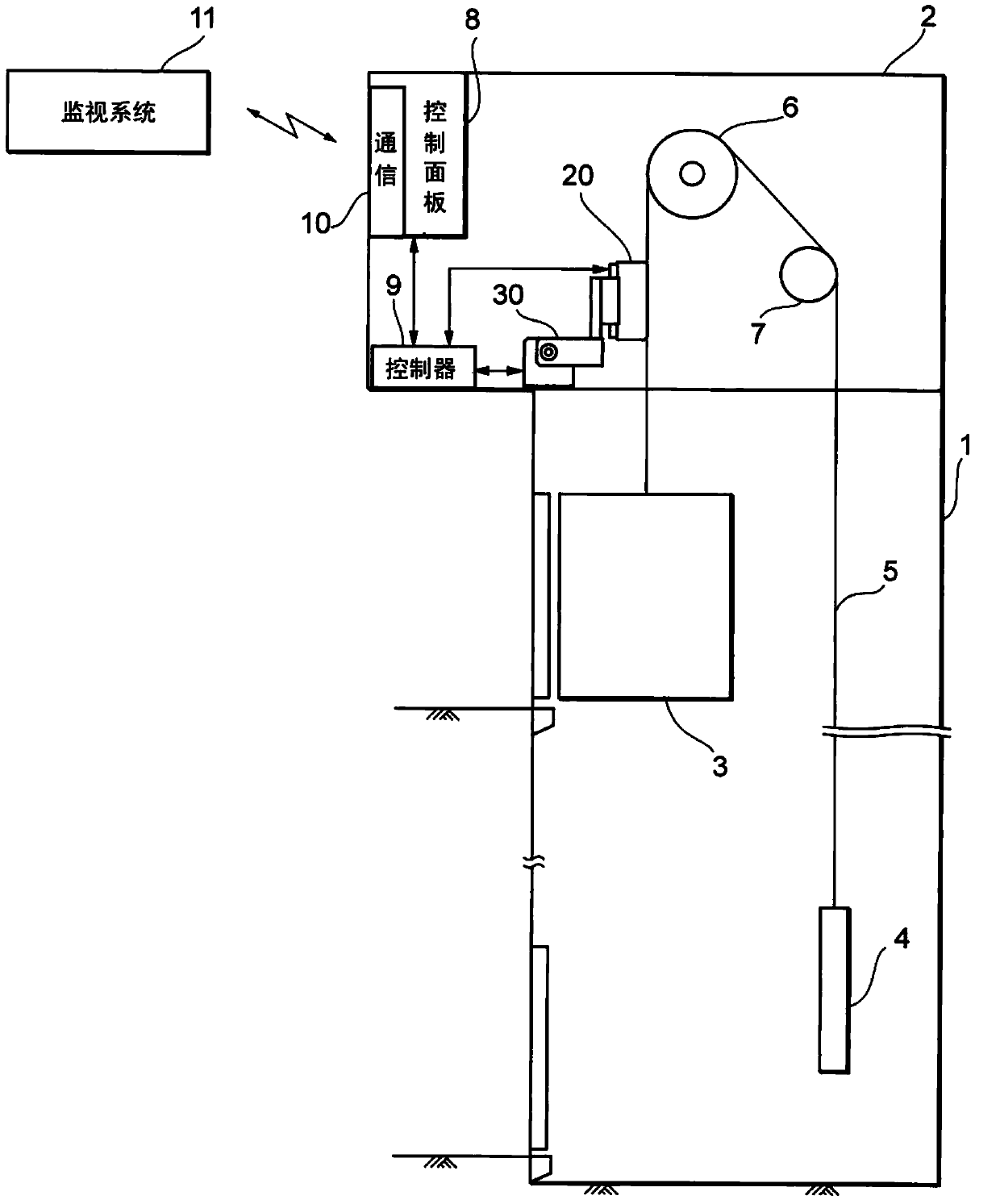
[0041] figure 1 The structure of the elevator is shown.

[0042] The elevator includes a hoistway 1, a machine room 2 provided above the hoistway 1, an elevator car 3 arranged to move up and down in the hoistway 1 to carry passengers and goods, and wire ropes 5, One end of the wire rope is fixed to the upper part (outside the roof) of the elevator car 3 and its other end is fixed to a balancer weight 4 . Usually, a plurality of wire ropes 5 arranged parallel to each other are used for the elevator. In this embodiment, four wire ropes 5 arranged in parallel are used. exist figure 1 , for clarity, only one of the wire ropes 5 is shown.

[0043] The middle part of each of the four wire ropes 5 travels (runs) through the machine room 2 , winds a hoist 6 and is applied to a deflector sheave 7 provided in the machine room 2 . An elevator control panel 8 including a communication device 10 is provided in the machine room 2 to control the hoist 6 . As the hoist 6 rotates forward...


PUM


Abstract

An apparatus for wire rope inspection is provided with a rope detector (20) along a channel. Multiple parallel wire ropes (5) pass through the channel. The rope detector (20) is suitable for sensing leakage magnetic flux leaked from the magnified wire ropes (5). The rope detector (20) includes a sensor surface formed in a plane, and the length of the sensor surface is greater than the whole width of the multiple parallel wire ropes (5). If the leakage magnetic flux is sensed, the sensor surface of the rope detector (20) is configured to be parallel to a plane defined by the multiple parallel wire ropes (5) so as to in wire contact with the multiple wire ropes (5) and is configured to span the whole multiple parallel wire ropes (5).

Description

technical field [0001] The invention relates to a device for wire rope inspection, a device, a method and a program for wire rope damage determination. Background technique [0002] Devices are known for inspecting wire ropes for hoists and cranes for defects using the leakage flux method. The inspection equipment is carried to the location where the wire rope is to be inspected. The inspection equipment is attached to and set on the wire rope using the fixing jig manually. Signal cables, power cables, waveform monitors, etc. are also connected to the inspection equipment at this location. The operator watches the leakage flux-based waveform appearing on the waveform monitor and determines, for example, whether the wire rope is damaged. [0003] Thus, carrying the inspection equipment to each site for each inspection of the wire rope naturally requires the operator to move to the site and thus pay labor costs. This also requires a long inspection time. Furthermore, dete...

Claims


Application Information

Patent Timeline
IPC IPC(8): G01N27/83
CPCB66B5/0025B66B5/0087B66B11/06
Inventor 近藤城圣
Owner TOKYO ROPE MFG
Why Eureka
Try Eureka