
Gravitational acceleration measurement device and method

A technology of gravitational acceleration and measuring beam, applied in the field of measurement, can solve problems such as affecting the measurement, affecting the accuracy of the g value of the gravitational acceleration, and the reference prism cannot be stationary.

Active Publication Date: 2014-05-14
NAT INST OF METROLOGY CHINA
View PDF6 Cites 11 Cited by
  • Summary
  • Abstract
  • Description
  • Claims
  • Application Information

AI Technical Summary

Problems solved by technology

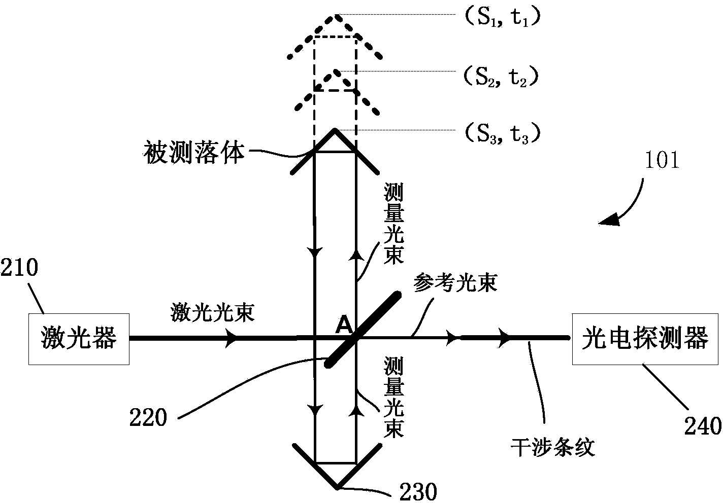
[0006] In order to ensure that the interference fringes generated during the fall of the measured falling object correspond to the change in the relative distance between the falling object and the earth, the reference prism must be stationary relative to the center of the earth. It is completely stationary relative to the center of the earth, and the resulting interference fringes contain the information of ground vibration, which affects the measurement of the distance of the measured falling object relative to the earth's motion
Therefore, the interference fringes generated by this laser interferometer do not completely correspond to the actual moving distance of the measured falling object relative to the earth, which affects the accuracy of the final gravitational acceleration g value

Method used


Image

  • Gravitational acceleration measurement device and method
  • Gravitational acceleration measurement device and method
  • Gravitational acceleration measurement device and method

Examples


Embodiment Construction

[0046] The following will clearly and completely describe the technical solutions in the embodiments of the present invention with reference to the accompanying drawings in the embodiments of the present invention. Obviously, the described embodiments are only some, not all, embodiments of the present invention. Based on the embodiments of the present invention, all other embodiments obtained by persons of ordinary skill in the art without creative efforts fall within the protection scope of the present invention.

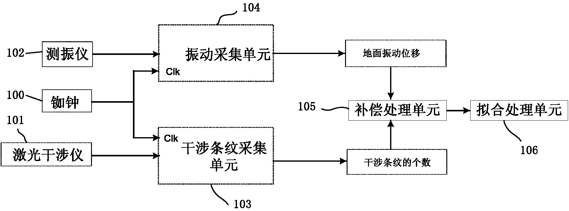
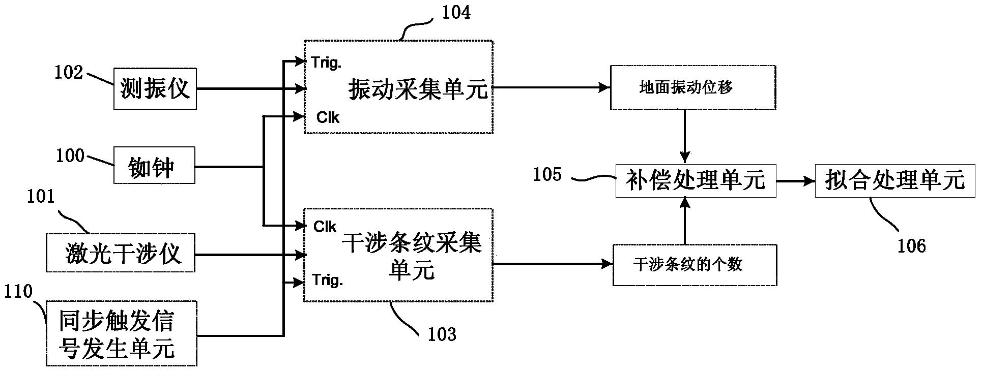
[0047] figure 1 It is a structural schematic diagram of an embodiment of the measuring device for the acceleration of gravity of the present invention. Such as figure 1 As shown, the measuring device for the acceleration of gravity provided by the present invention specifically includes: a rubidium clock 100, a laser interferometer 101, a vibrometer 102, an interference fringe acquisition unit 103, a vibration acquisition unit 104, a compensation processing unit 1...


PUM


Abstract

The embodiment of the invention discloses a gravitational acceleration measurement device and method. The device comprises a rubidium clock, a laser interferometer, a vibration meter, an interference fringe acquisition unit, a vibration acquisition unit, a compensation processing unit and a fitting processing unit, wherein the rubidium clock is used for measuring the fall time t of a measured falling body; the laser interferometer is used for generating interference fringes in the falling process of the measured falling body; the vibration meter is used for measuring ground vibration displacement; the interference fringe acquisition unit is used for acquiring the number of the interference fringes, and the number of the interference fringes is used for calculating the fall displacement X of the measured falling body; the vibration acquisition unit is used for acquiring the ground vibration displacement of the vibration meter, and the ground vibration displacement is used for indicating displacement Y of a reference prism; the compensation processing unit is used for obtaining the actual falling displacement S of the measured falling body within the fall time t according to the formula S=X-Y; the fitting processing unit is used for conducting least squares fitting on three or more data sets (S, t) of falling time t and corresponding actual falling displacement S to obtain the numerical value of gravitational acceleration g. A more accurate numerical value of gravitational acceleration g can be obtained through the gravitational acceleration measurement device and method.

Description

technical field [0001] The invention relates to measurement technology, in particular to a measurement device and a measurement method for acceleration of gravity. Background technique [0002] At present, the main tool used to measure the g value of the acceleration of gravity is the absolute gravimeter, and the methods used mainly include classical measurement method and atomic interferometry method. The classic absolute gravimeter, also known as the free-falling absolute gravimeter, obtains the acceleration of gravity by accurately measuring the displacement and time of the falling body in the gravitational field. Its mathematical expression is: [0003] S(t)=-1 / 2gt 2 +v 0 t+s 0 (1.1) [0004] Among them, g, v 0 and s 0 are the acceleration of gravity, initial velocity and initial displacement, respectively, and t and S(t) are the time and displacement of free fall, respectively. Simplify the model, ignore the spatial variation of the acceleration of gravity, and ...

Claims


Application Information

Patent Timeline
IPC IPC(8): G01V7/14
Inventor 吴书清李春剑粟多武徐进义
Owner NAT INST OF METROLOGY CHINA
Learn More