
Liquid crystal display

Inactive Publication Date: 2008-06-26
INNOLUX CORP +1
View PDF1 Cites 23 Cited by
  • Summary
  • Abstract
  • Description
  • Claims
  • Application Information

AI Technical Summary

Benefits of technology

[0033]Advantages of the apparatuses and methods may include one or more of the following. A transflective display using a chiral material having a twist direction different (e.g., opposite) from the twist direction induced by alignment layers can have matching transmissive and reflective optical characteristics, so that a single switching device can be used to control the transmissive and reflective parts of a pixel. A display (e.g., reflective or transflective) using a chiral material having a twist direction different (e.g., opposite) from the twist direction induced by alignment layers can have very little color dispersion. In the bright state, the polarization of light is changed due to the polarization rotating (wave guiding) effect caused by twisted structure of liquid crystal layer and the phase retardation effect caused by the reversely twisted structure in the bulk area.

Problems solved by technology

For example, displays having different sizes can use different liquid crystal modes due to considerations in device fabrication complexity, manufacturing costs, and system performances.
In the dark state, there can be light leakage caused by optical retardation at the surface regions of the liquid crystal layer because the liquid crystal molecules near the surface regions are not switched perpendicular to the substrate due to the binding force of the alignment layers.

Method used


Image

  • Liquid crystal display
  • Liquid crystal display
  • Liquid crystal display

Examples


Embodiment Construction

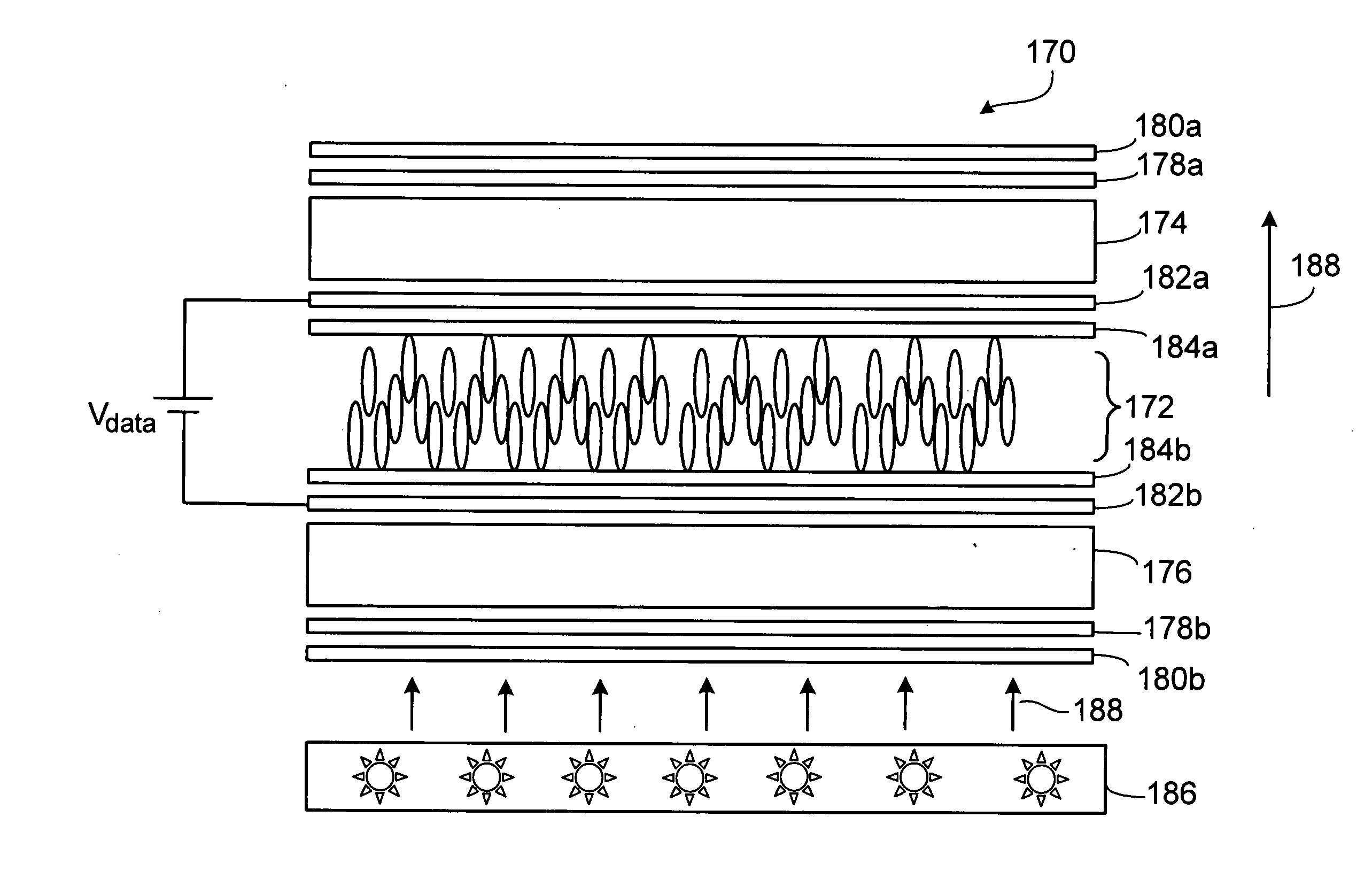
[0047]FIG. 1 is a cross sectional diagram of a vertical alignment mode liquid crystal display 170 using a chiral material that induces a twisted structure in a liquid crystal layer 172 having a twist direction that is opposite to the twist direction induced by alignment layers. The liquid crystal layer 172 is positioned between an upper substrate 174 and a lower substrate 176 that are parallel to each other. Broadband quarter wave retardation films 178a and 178b are attached on the outer side of upper and lower substrates 174 and 176, respectively. Linear polarizers 180a and 180b are attached to the retardation films 178a and 178b, respectively. The retardation films 178a and 178b can be selected to achieve a wide viewing angle. The inner sides of the substrates 174 and 176 have transparent electrodes 182a and 182b coated with alignment layers 184a and 184b, respectively. A backlight module 186 generates light 188 that is modulated by the various layers. A data voltage Vdata is appl...


PUM


Abstract

A liquid crystal display includes a first substrate having a first electrode and a first alignment film, a second substrate having a second electrode and a second alignment film, and a liquid crystal layer having liquid crystal molecules between the first and second substrates. The liquid crystal layer is doped with a chiral material that tends to induce a twist in directors of the liquid crystal molecules when an electric field is applied to the liquid crystal layer using the first and second electrodes. The first alignment film has a first alignment direction, the second alignment film has a second alignment direction, and the first and second alignment films have orientations that tend to induce a twist in the directors when an electric field is applied to the liquid crystal layer, in which the direction of twist induced by the first and second alignment films is different from the direction of twist induced by the chiral material. The display includes a reflective layer to reflect external light that passes a first portion of the liquid crystal layer. The external light is modulated by the first portion of the liquid crystal layer.

Description

CROSS-REFERENCE TO RELATED APPLICATIONS[0001]This application is related to concurrently filed application Ser. No. ______, titled “Liquid Crystal Display” (attorney docket 14509-056001), the contents of which are incorporated by reference.BACKGROUND OF THE INVENTION[0002]The description relates to liquid crystal displays.[0003]Liquid crystal displays (LCDs) can be used in, e.g., portable devices, computers displays, and high definition televisions. A liquid crystal display can have a liquid crystal layer and two crossed linear polarizers for modulating light using an electro-optic effect. An external voltage applied to the liquid crystal layer changes the orientations of the liquid crystal molecules and the optical phase retardation of the liquid crystal layer, thereby changing the amount of light that passes the crossed linear polarizers. Each pixel of the display can show a range of gray scale levels depending on the voltage applied to the liquid crystal layer. Color filters can ...

Claims


Application Information

Patent Timeline
IPC IPC(8): G02F1/1337G02F1/1335
CPCG02F1/133555G02F1/1396G02F1/133753
Inventor LEE, JU-HYUNWU, SHIN-TSONLI, WANG-YANGWEI, CHUNG-KUANG
Owner INNOLUX CORP
Learn More