A Polarization Self-Matching Beam Reversal Method

A self-matching, beam technology, applied in the direction of electrical components, antennas, etc., can solve the problems of increased loss, difficulty in determining the polarization mode of the reverse beam, and mismatching of the polarization of the receiving and receiving beams, so as to reduce the phase error and improve the reverse Accuracy and the effect of reducing the local oscillator frequency

Active Publication Date: 2015-11-25
XIAN INSTITUE OF SPACE RADIO TECH
View PDF3 Cites 0 Cited by
  • Summary
  • Abstract
  • Description
  • Claims
  • Application Information

AI Technical Summary

Problems solved by technology

However, it is difficult to determine the polarization mode of the reverse beam without knowing the antenna state of the receiving end. At the same time, due to the position change and rotational movement of the transmitting and receiving ends, it will also cause the problem of polarization mismatch and increased loss of the transmitting and receiving ends.

Method used


Image

  • A Polarization Self-Matching Beam Reversal Method
  • A Polarization Self-Matching Beam Reversal Method
  • A Polarization Self-Matching Beam Reversal Method

Examples


Embodiment Construction

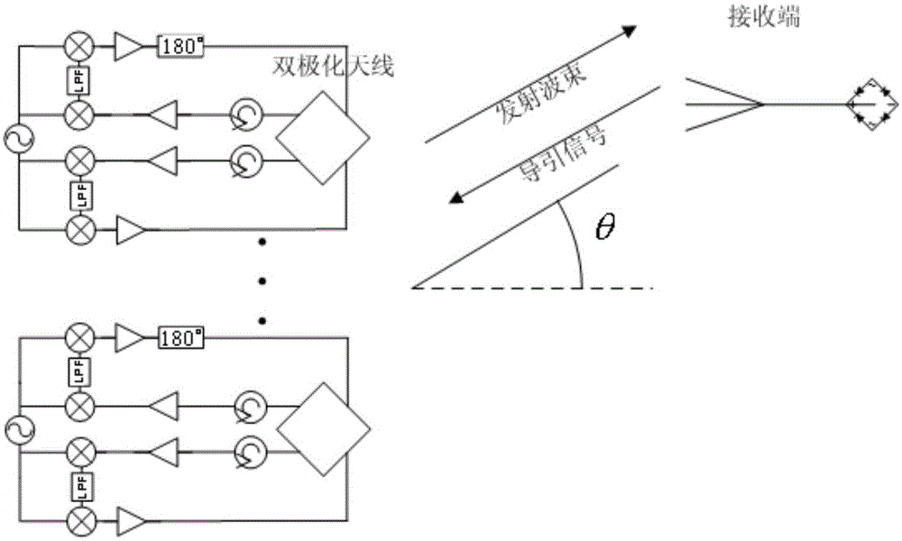
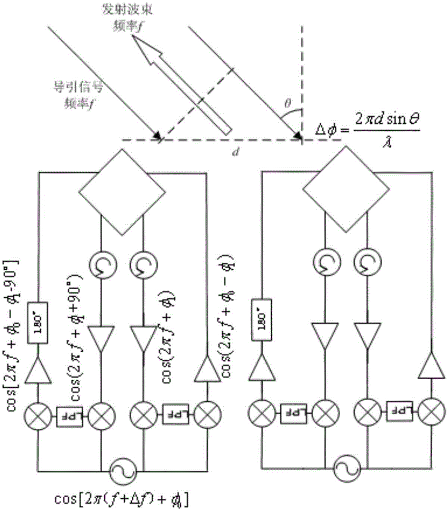
[0018] Such as figure 1 As shown, it is a simplified diagram of the polarization self-matching beam inversion system. In the figure, the distance between the antenna elements of the antenna array at the transmitting end is d, and the local oscillator frequency at the transmitting end is f+Δf. The frequency of the pilot signal transmitted by the receiving end is f, and the relationship between the pilot signal received by the transmitting end and the transmitting beam is as follows: figure 2 shown.

[0019] exist figure 2 In this method, the position information of the receiving end is obtained through the heterodyne circuit structure of fractional frequency mixing, and the beam alignment and adaptive tracking of the power synthesis are realized. The polarizations of the pilot signals are orthogonal. The pilot signal received by each dual-polarized antenna is divided into two paths, which are amplified by a duplexer and an amplifier, and are respectively a first receiving ...


PUM


Abstract

The invention discloses a polarization self-matching type wave beam reversing method. The polarization self-matching type wave beam reversing method aims to solve the problem that in systems such as microwave energy transmission systems and energy-carrying communication systems, when the antenna polarization mode of a receiving end is unknown to a sending end or the polarization direction is changed due to movement or rotation of the receiving end, the antenna polarization mode of the receiving end and the antenna polarization mode of the sending end are not matched, link loss is increased, and energy or information transmission efficiency is affected. The polarization self-matching type wave beam reversing method comprises the steps that guide signals are received through a square double-fed SMD dual polarized antenna unit of an antenna array of the sending end, one receiving branch of two receiving branches passes through a 180-degree delay line to enable the phase differences of the two branches of signals to be reversed, polarization rotation is completed, and dual polarized antennae are fed in for transmission, the guide signals are received in a frequency-mixing mode by several times to enable phase distribution of conjugation to be obtained, and transmitted wave beams are made to aim at the receiving end in a self-adaptive mode. The polarization self-matching type wave beam reversing method has the advantages that priori knowledge such as the positional information of the receiving end and the polarization mode of a receiving antenna is not needed, a reversing array can generate transmitting wave beams in the direction identical to the direction of the guide signals and with orthorhombic polarization modes, and duplexing work is achieved.

Description

technical field [0001] The invention belongs to the field of microwave communication, and relates to a method for reversing antenna beams, which is used for energy or information receiving ends to form antenna beams with adaptive polarization matching and precise direction alignment. Background technique [0002] In systems such as mobile communication, microwave energy transmission, and energy-carrying communication, in addition to accurately aligning the beam synthesized by the transmitting antenna array with the receiving unit, it is also necessary to match the antenna polarization modes at both ends of the transmitting and receiving ends, so as to achieve high efficiency. energy or information transmission. [0003] The reverse antenna array can accurately align the beam at the receiving end by using the pilot signal sent by the receiving end without requiring the position information of the receiving end. The inverted array is realized by inverting the phase distributi...

Claims


Application Information

Patent Timeline
Patent Type & Authority Patents(China)
IPC IPC(8): H01Q15/24H01Q3/30
Inventor 董亚洲董士伟王颖
Owner XIAN INSTITUE OF SPACE RADIO TECH
Why Eureka
Try Eureka