Terminal connector

A terminal connector and integrated technology, applied in the direction of multi-core cable end parts, etc., can solve the problems of large insertion force, large contact wear, instability, etc., to achieve stable and tight surface contact, large line flow capacity, The effect of small contact resistance

Inactive Publication Date: 2014-05-14
XIAN BLUE DIAMOND ELECTRONICS
View PDF0 Cites 0 Cited by
  • Summary
  • Abstract
  • Description
  • Claims
  • Application Information

AI Technical Summary

Problems solved by technology

[0005] The purpose of the present invention is to provide a terminal connector, which solves the problem of poor contact between the contact piece and the plug, temperature rise, unstable clamping force, large and unstable insertion and withdrawal force, and wear of the contact piece of the existing terminal connector. Large, easily deformed, affecting the stability of terminal connectors

Method used


Image

  • Terminal connector
  • Terminal connector
  • Terminal connector

Examples


Embodiment Construction

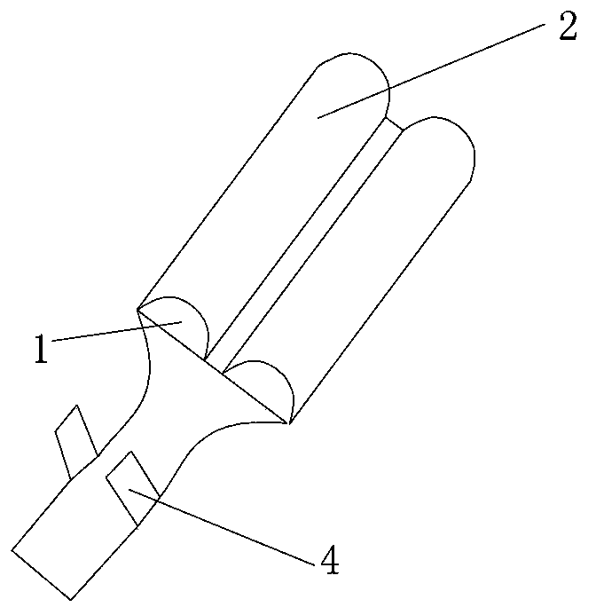
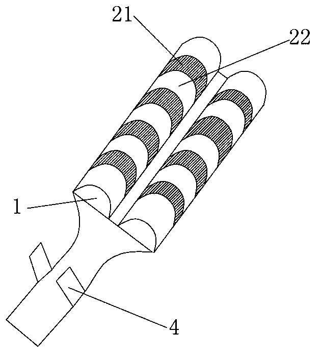
[0023] Such as figure 2 , A terminal connector, comprising a flat part 1, the lower end of the flat part 1 is connected to the terminal 4, the left and right ends of the flat part 1 are respectively bent to form a bent part 2, the bent part 2 is from the flat part 1 A plurality of mutually parallel strip-shaped bending portions 22 are respectively formed by bending the left and right ends toward each other, and the cross section of the bending portion 2 is semicircular arc shape. The number of strip-shaped bent portions 22 is two or more.

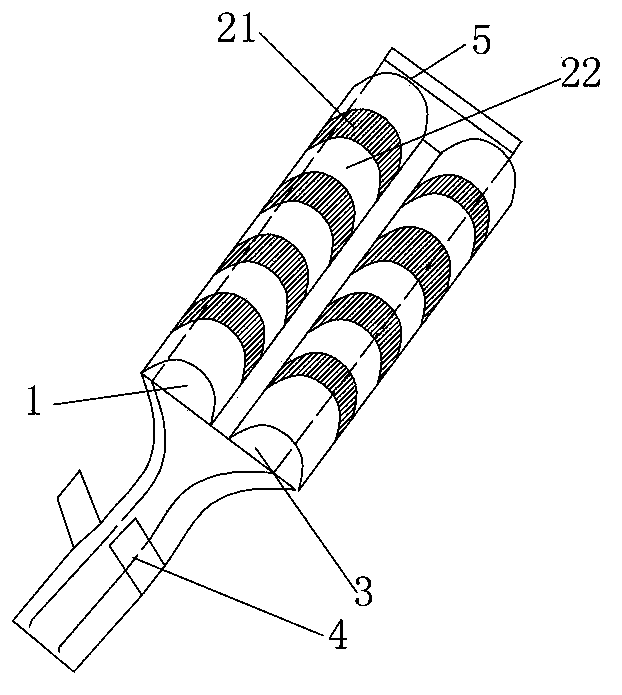
[0024] There is a gap 21 between two adjacent strip-shaped bent portions 22, or there may be no gap 21 therebetween. A corner of the free end of the bent portion 2 close to the entrance is provided with a chamfer 5 structure to facilitate plug insertion.

[0025] Such as image 3 A partition 3 is provided between the free end of the bent portion 2 and the flat portion 1, and one end of the partition 3 is fixed. Specifically, the upper end of...


PUM


Abstract

The invention provides a terminal connector which helps to solve the problem that in a conventional terminal connector, a contact piece is in poor contact with a plug, temperature rise is high, clamping force is unstable, insertion and extraction force are big and not stable, wear extent of the contact piece is large and the contact piece is easy to deform, and thus the stability of the terminal connector is influenced. The terminal connector comprises a plane portion. The lower end of the plane portion is connected with a wiring terminal. The left and right ends of the plane portion bend face to face to form bending portions. The bending portions are a plurality of mutually-parallel bar-shaped bending portions formed by bending the left and right ends of the plane portion face to face, the cross section of the bending portion being in half circular arc shape. The bar-shaped bending portions enable one surface of a plug and a connector terminal to change from point contact to multi-point contact, and the surface contact on the other surface to be much more stable and closer; line circulation capability is big; contact resistance is small; and heat amount is low.

Description

Technical field [0001] The invention relates to a terminal connector. Background technique [0002] The existing connector terminal includes a flat part, the lower end of the flat part is connected to the terminal, the left and right ends of the flat part are respectively bent toward each other to form a bent part, and the distance between the free end of the bent part and the flat part is smaller than the thickness of the plug When the plug is inserted into the gap between the flat part and the free end of the bending part, the plug is closely matched with the flat part under the action of the elastic force of the bending part. [0003] This structure has the following disadvantages: when the plug is inserted into the gap between the flat part and the free end of the bending part, one side of the plug is in close contact with the flat part to form a surface contact, and the other surface is in close contact with the free end of the bending part to form a line This kind of line co...

Claims


Application Information

Patent Timeline
Patent Type & Authority Applications(China)
IPC IPC(8): H01R11/11
Inventor 王水平
Owner XIAN BLUE DIAMOND ELECTRONICS
Why Eureka
Try Eureka