Non-contact charging apparatus for mobile body and non-contact charging method for mobile body

A technology of non-contact charging and moving objects, which is applied in the direction of circuit devices, battery circuit devices, electric vehicle charging technology, etc. It can solve the problems of power receiving coils, secondary battery charging difficulties, and the inability to improve power transmission efficiency. efficiency effect

Inactive Publication Date: 2014-05-14
HITACHI LTD
View PDF6 Cites 19 Cited by
  • Summary
  • Abstract
  • Description
  • Claims
  • Application Information

AI Technical Summary

Problems solved by technology

[0006] Mobile bodies such as electric vehicles are restricted by the size and shape of the place where the power receiving device can be installed, and it is difficult to charge the secondary battery mounted on the mobile body in a short time
For example, in the case of installing a power receiving coil on the floor of the vehicle body, it is difficult to install a power receiving coil with a sufficient area, and there is a problem that the power transmission efficiency cannot be improved.

Method used


Image

  • Non-contact charging apparatus for mobile body and non-contact charging method for mobile body
  • Non-contact charging apparatus for mobile body and non-contact charging method for mobile body
  • Non-contact charging apparatus for mobile body and non-contact charging method for mobile body

Examples


Embodiment 1

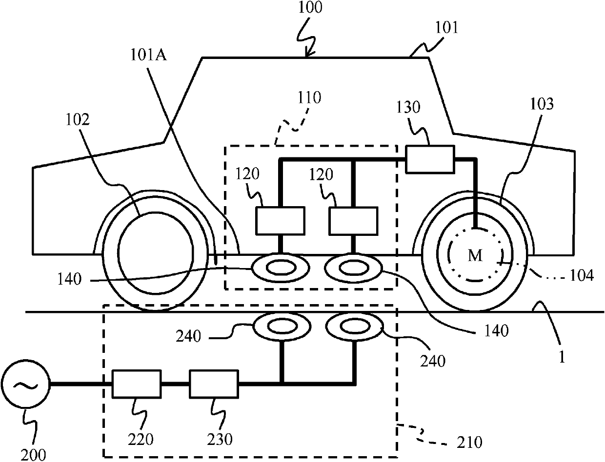
[0033] use figure 1 as well as figure 2 The first embodiment will be described. figure 1 An example is shown in which an electric vehicle 100 serving as a "mobile body" is provided with a non-contact charging device for a mobile body.

[0034] The electric vehicle 100 includes, for example, a vehicle body 101 , front wheels 102 , rear wheels 103 , an electric motor 104 , a steering device, a lighting device, an air conditioner (none of which are shown in the figure), and the like. In this embodiment, the case of rear wheel drive is shown, and the electric motor 104 is provided inside the wheel of the rear wheel 103, for example.

[0035] In addition, the configuration of the electric vehicle 100 is an example, and may be a front-wheel drive system, or may be all four-wheel drive. In addition, as the moving body, an electric truck, an electric two-wheeled vehicle, an electric wheelchair, an electric one-person moving body (that is, a personal vehicle) and the like can be ap...

Embodiment 2

[0048] use image 3 Next, the second embodiment will be described. Since each of the following examples including this example corresponds to a modified example of the first example, the description will focus on differences from the first example.

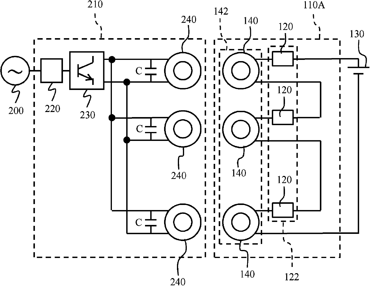
[0049] Power reception device 110A of this embodiment connects a plurality of power reception coils 140 and AC-DC conversion device 120 in series, and stores received electric power in secondary battery 130 . Reference numeral 142 is assigned to the power receiving coils connected in series, and reference numeral 122 is assigned to the AC-DC converters connected in series for description.

[0050] The present embodiment thus constituted also exhibits the same effects as those of the first embodiment. Furthermore, in this embodiment, since the power receiving coils 140 are connected in series, the charging voltage to the secondary battery 130 can be increased, and a desired voltage value can be obtained.

Embodiment 3

[0052] use Figure 4 The third embodiment will be described. In the power receiving device 110B of this embodiment, the power receiving coil group 141 and the AC-DC converting device group 121 (parallel connection group) connected in parallel, and the power receiving coil group 142 and the AC-DC converting device group 122 (series connection group) connected in series connection group) are connected in parallel to charge the secondary battery 130 .

[0053] Focusing on the power transmitting device 210, only the power receiving coil 140 included in the power receiving device 110B is added, and the power transmitting device 210 described in the first embodiment is different from the power transmitting device 210 described in the first embodiment except that the power transmitting coil 240 and the resonant capacitor C are also increased. have the same structure.

[0054] The present embodiment thus constituted also exhibits the same effects as those of the first embodiment. F...


PUM


Abstract

A non-contact charging apparatus for mobile body and a non-contact charging method for a mobile body are disclosed. The present invention efficiently transmits electric power in a non-contact manner to a mobile body having constraints with respect to the installation of a receiving part therein. A non-contact charging apparatus for a mobile body has a power-receiving device (110) disposed in an electric car (100), and a power-transmitting device (210) disposed in a manner of non-contact with the power-receiving device. The power-receiving device has a plurality of power-receiving coils (140) distributively arranged in prescribed locations of the electric car to receive electric power from the outside. The power-transmitting device has a plurality of power-transmitting coils (240) arranged in prescribed locations outside of the electric car corresponding to the plurality of power-receiving coils to transmit electric power. The non-contact charging apparatus for a mobile body transmits electric power in a non-contact manner from the plurality of power-transmitting coils to the plurality of power-receiving coils and charges a secondary battery (130). Since a plurality of power-receiving coils are provided, electric power can be transmitted efficiently even when there are installation-space or installation-shape constraints.

Description

technical field [0001] The present invention relates to a non-contact charging device for a mobile body and a non-contact charging method for a mobile body. Background technique [0002] With the improvement of environmental awareness and the technical development of secondary batteries and electric motors, various electric vehicles such as electric cars, electric buses, electric trucks, and electric two-wheeled vehicles have been proposed. These electric vehicles charge a secondary battery, and use the electric power extracted from the secondary battery to drive an electric motor to obtain propulsion. [0003] It is known that a cable is connected to a secondary battery for charging, or a non-contact method is used to charge a secondary battery. However, since the method of using a cable is cumbersome, the development of a non-contact charging method is expected (Patent Document 1, 2). [0004] Patent Document 1: JP Unexamined Publication No. 2011-258807 [0005] Patent ...

Claims


Application Information

Patent Timeline
Patent Type & Authority Applications(China)
IPC IPC(8): H02J7/02H02J17/00H02J7/00
CPCY02T90/14Y02T10/7072B60L53/122B60L53/126H02J2310/48Y02T10/70H02J50/402H02J50/12Y02T90/12B60L53/12H02J7/00
Inventor 今津真当麻贵则立川真马场淳片山敏男
Owner HITACHI LTD
Why Eureka
Try Eureka