Rotor and rotating electric machine having the same

A technology of rotating electrical machines and rotors, applied in synchronous motors with stationary armatures and rotating magnets, electric components, electrical components, etc., to achieve the effects of improving rotational balance, improving magnetic properties, and increasing output

Active Publication Date: 2014-05-14
DENSO CORP
View PDF2 Cites 6 Cited by
  • Summary
  • Abstract
  • Description
  • Claims
  • Application Information

AI Technical Summary

Problems solved by technology

However, there is no description regarding the specific shapes such as the radius of curvature of the outer wall surface of the through hole and the polar portion of the core body.

Method used


Image

  • Rotor and rotating electric machine having the same
  • Rotor and rotating electric machine having the same
  • Rotor and rotating electric machine having the same

Examples


no. 1 approach )

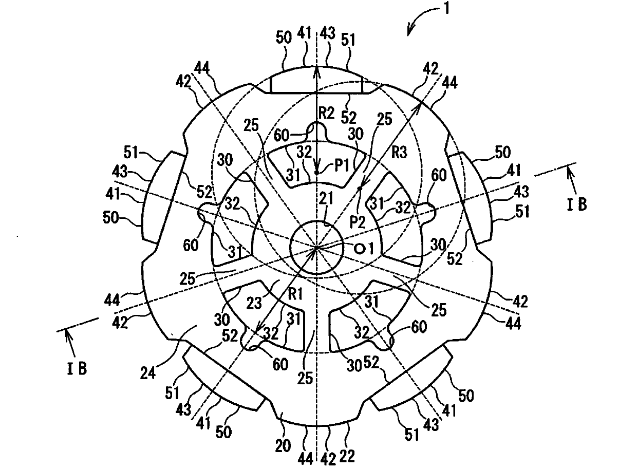
[0017] A rotor 1 according to a first embodiment is shown in Figure 1A and Figure 1B , and a rotating electrical machine 10 using this rotor 1 is shown in figure 2 middle.

[0018] The rotary electric machine 10 is used, for example, as a drive source (for example, a motor) of an electric power steering apparatus that assists a steering operation of a vehicle or the like. Such as figure 2 As shown, the rotating electric machine 10 includes a rotor 1 , a stator 70 , a motor shaft 2 and a motor housing 3 .

[0019] Such as Figure 1A and Figure 1B As shown, the rotor 1 includes a core body 20 , a through hole 30 , a first polarity portion 41 , a second polarity portion 42 and a magnet 50 . The through hole 30 may correspond to the first through hole.

[0020] The core body 20 has a substantially cylindrical shape obtained by laminating thin plates such as metal plates. The core body 20 has an axial hole 21 defined around the axis O1 and passing through the core body 2...

no. 1 approach

[0021] The through hole 30 has a generally fan-shaped cross-section and penetrates the core body 20 in the thickness direction. According to the first embodiment, the core body 20 has five through holes arranged at regular intervals in the circumferential direction of the core body 20 . The through hole 30 is one of five through holes. The through hole 30 is located between the axis O1 of the core body 20 and the outer wall 22 in the radial direction.

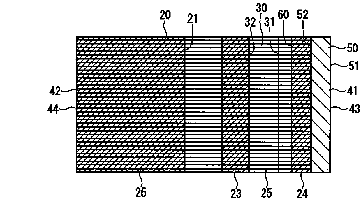
[0022] Furthermore, in a cross section taken along a line perpendicular to the axis O1, the through hole 30 has a substantially fan-shaped shape. The through hole 30 has an arcuate surface 31 and an arcuate surface 32 . The distance from the axis O1 to the arc surface 31 is greater than the distance from the axis O1 to the arc surface 32 . The arcuate surface 31 defines a curved wall such that the distance from the axis O1 to the point of the curved wall of the arcuate surface 31 is constant. The arcuate face 32 defines a c...

Embodiment approach

[0023] By providing the through hole 30 , the annular portion 23 is defined between the shaft hole 21 and the through hole 30 . The core body 20 has an annular portion 24 located outside the through hole 30 in the radial direction. The core body 20 also has spoke portions 25 . The spoke portions 25 and the through holes 30 are alternately arranged in the circumferential direction. The spoke portions 25 extend from the annular portion 23 to the annular portion 24 in the radial direction. According to the first embodiment, the core body 20 has five spoke portions, and the spoke portion 25 is one of the five spoke portions.

[0024] The first polar portion 41 is positioned to define the outer wall 22 of the core body 20 in the radial direction. The first polarity portions 41 and the second polarity portions 42 are alternately arranged in the circumferential direction. According to the first embodiment, the rotor 1 has five first polarity portions 41 and five second polarity p...


PUM


Abstract

A rotor for a rotating electric machine has a core body (20) and a magnets (50,53). The core body has a through-hole (30), a first polar portion (41), and a second polar portion (42). The first polar portion and the second polar portion are alternately arranged in the circumference direction. The magnets are disposed on the core body at a position corresponding to the first polar portion or the second polar portion. The through-hole has an arc-shaped surface (31) having a first curvature radius (R1). The first polar portion has an arc-shaped surface (43) having a second curvature radius (R2). The second polar portion has an arc-shaped surface (44) having a third curvature radius (R3). The first curvature radius is larger than or equal to the second curvature radius (R1>=R2). The first curvature radius is larger than or equal to the third curvature radius (R1>=R3).

Description

technical field [0001] The present disclosure relates to a rotor and a rotating electrical machine having the rotor. Background technique [0002] Conventionally, it is known that a rotor has a core body including through holes. For example, JP-2012-143090A (corresponding to US2012 / 0169163A1) discloses a rotor having a core body including five through holes arranged at regular intervals in the circumferential direction of the core body. By providing five through holes, the rotor can be lighter in weight and can have less inertia. [0003] In general, when the core body has through holes, the rotational balance, magnetic balance and strength of the rotor may be reduced. According to the rotor disclosed in JP-2012-143090A, the core body has spoke portions. The spoke portions and the through holes are alternately arranged in the circumferential direction. By providing the spoke portions, the strength of the core body can be restricted from being lowered. Further, by design...

Claims


Application Information

Patent Timeline
Patent Type & Authority Applications(China)
IPC IPC(8): H02K1/27
CPCH02K7/04H02K1/2746H02K1/28H02K21/14H02K2213/03
Inventor 内藤昭仁
Owner DENSO CORP
Why Eureka
Try Eureka