System for cooling coil

A winding and winding head technology, applied in electric components, electromechanical devices, electrical components, etc., can solve the problems of insufficient cooling of the winding head and low air thermal conductivity, and achieve long service life, enhanced firmness, and low susceptibility to interference. sexual effect

Inactive Publication Date: 2014-05-14
SIEMENS AG
View PDF7 Cites 4 Cited by
  • Summary
  • Abstract
  • Description
  • Claims
  • Application Information

AI Technical Summary

Problems solved by technology

Due to the low thermal conductivity of air, the cooling of the winding heads is in many cases insufficient and must be supported by other measures

Method used


Image

  • System for cooling coil
  • System for cooling coil
  • System for cooling coil

Examples


Embodiment Construction

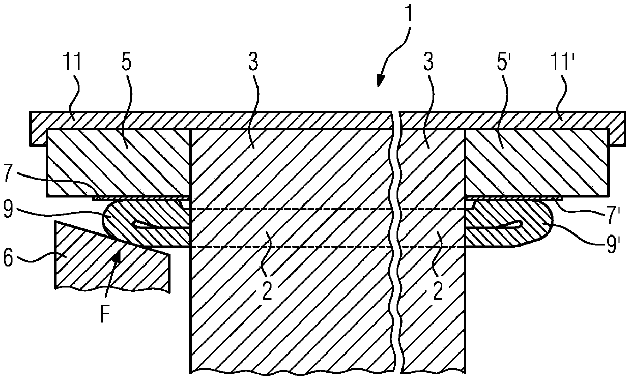
[0029] figure 1A schematic side view of a first exemplary embodiment of a system for cooling a winding is shown. This system consists of a laminated core 3 in which the winding 2 is embedded, and heat-conducting elements 5, 5' which bear against the laminated core 3 at the end sides. The heat conducting parts 5, 5' are fixed together with the lamination stack 3 by means of clips 11, 11'. The clips 11, 11' here extend from one end of the heat-conducting part 5 to the opposite end of the laminated core 3. exist figure 1 In the case of the manner shown in , the clip 11' also surrounds the oppositely arranged second heat conducting part 5'. As shown, the clips 11, 11' can be bent around the outer edges of the heat-conducting parts 5, 5' in order to achieve a non-positive connection of the heat-conducting parts 5, 5' and the laminated core 3. As shown by the thin layer between the winding head 9, 9' and the heat conducting part 5, 5', a thin electrical insulation 7 may be inser...


PUM


Abstract

The present invention relates to a system for cooling a coil (2), particularly in a rotating motor (1). The system comprises a thermal conductive component (5, 5') having an end side abutting against a lamination group (3) and being in thermal conductive contact with a coil head (9, 9') of the coil (2). The system is characterized in that the thermal conductive contact between the coil head (9, 9') and the thermal conductive component (5, 5') is ensured by the press-fit connection between the coil head (9, 9') and the thermal conductive component (5, 5'), so that the coil head (9, 9') is at least in sections in direct contact with the thermal conductive component (5, 5').

Description

technical field [0001] The invention relates to a system for dissipating heat from a winding, in particular of a rotating electric machine, having a heat-conducting part which bears at the end side against a laminated core and is in thermally conductive contact with the winding head. Furthermore, the invention relates to a stator, a rotor and a rotating electric machine each having such a system. Background technique [0002] A rotating electric machine is, for example, an electric motor or a generator for generating electric current. Electric motors and generators are generally used in fields requiring high and stable output power while being relatively small in size and weight. Such fields of application are, for example, wind power plants, electric vehicles or the field of industrial manufacturing. These fields combine the requirements for high and stable active power with simultaneously long service life and low failure rate. To achieve this goal, adequate cooling of ...

Claims


Application Information

Patent Timeline
Patent Type & Authority Applications(China)
IPC IPC(8): H02K9/22H02K15/04
CPCY02E10/72H02K9/223
Inventor 克劳斯·比特纳克劳斯·希尔克纳
Owner SIEMENS AG
Why Eureka
Try Eureka