Welding spot area fully stirred key-hole-free friction stir spot welding method and tool

A technology of solder joint area and friction point, which is applied in the field of keyhole friction spot welding, can solve the problems of complex tissue distribution, achieve the effect of improving spot welding joint structure, improving joint performance, and smoothing the surface of solder joints

Active Publication Date: 2014-05-21
AVIC BEIJING AERONAUTICAL MFG TECH RES INST
View PDF9 Cites 7 Cited by
  • Summary
  • Abstract
  • Description
  • Claims
  • Application Information

AI Technical Summary

Problems solved by technology

[0005] The purpose of the present invention is to solve the problems existing in the existing backfill friction stir spot welding technology, and provide a full-stirring keyhole friction spot welding tool in the welding spot area, which can effectively eliminate backfill friction stir spot welding Defects with complex head tissue distribution while retaining a keyhole-free surface for friction spot welded joints
[0006] Another object of the present invention is to provide a friction spot welding tool that can effectively eliminate the defect of complex structure distribution of the backfill friction stir spot welding joint, and at the same time retain the fullness of the keyhole-free solder joint area on the surface of the backfill friction stir spot welding joint. Stirring keyhole friction spot welding method

Method used


Image

  • Welding spot area fully stirred key-hole-free friction stir spot welding method and tool
  • Welding spot area fully stirred key-hole-free friction stir spot welding method and tool
  • Welding spot area fully stirred key-hole-free friction stir spot welding method and tool

Examples


Embodiment Construction

[0037] The details of the present invention can be understood more clearly with reference to the accompanying drawings and the description of specific embodiments of the present invention. However, the specific embodiments of the present invention described here are only for the purpose of explaining the present invention, and should not be construed as limiting the present invention in any way. Under the teaching of the present invention, the skilled person can conceive any possible modification based on the present invention, and these should be regarded as belonging to the scope of the present invention.

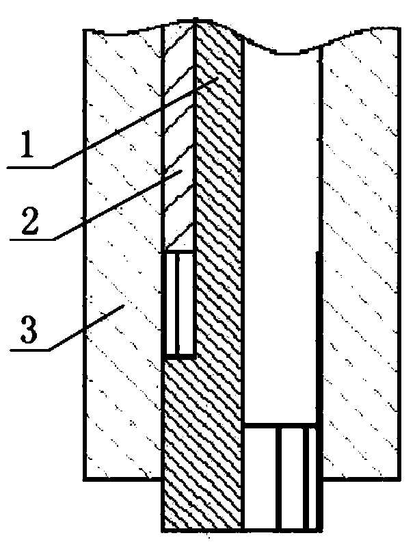
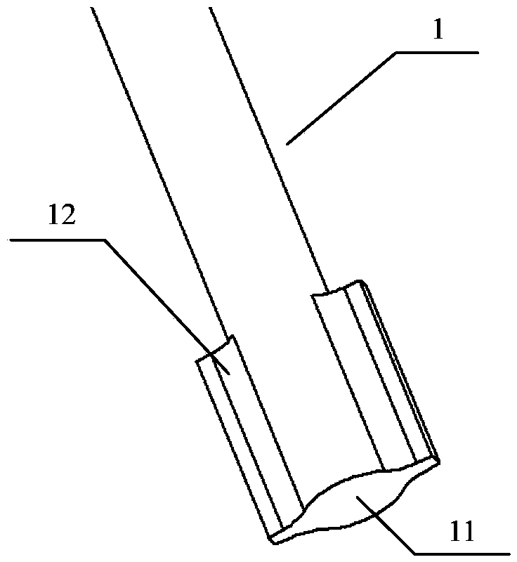
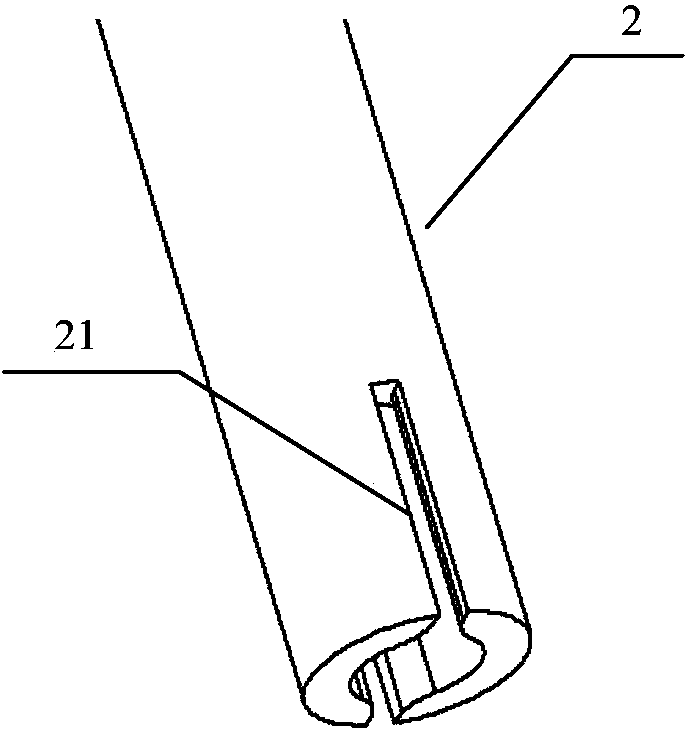
[0038] Please refer to figure 1 , Figure 2A , Figure 2B , Figure 2C, are respectively the schematic diagram of the structure of the full-stirred keyhole friction spot welding tool in the welding spot area of ​​the present invention; the partial structural diagrams of the stirring needle, the shaft shoulder and the compression sleeve of the present invention. The in...


PUM


Abstract

The invention discloses a welding spot area fully stirred key-hole-free friction stir spot welding method and tool. The tool comprises a stirring needle, a shaft shoulder, and a clamp sleeve which are sequentially sleeved from inside to outside and are arranged in a relatively sliding manner, at least two stirring raised ribs are uniformly distributed peripherally on the outer wall of a stirring end of the stirring needle, a holding notch matched with the stirring raised rib is formed in the end face of the shaft shoulder, the stirring raised rib can stretch along the holding notch, and the end face of the stirring end of the stirring needle and the end face of the shaft shoulder and the clamp sleeve are on the same horizontal plane. According to the method and the tool provided by the invention, the defect of complicated distribution of a backfill friction stir spot welding joint is effectively eliminated, and meanwhile, the advantage that no key hole is left in the surface of the backfill friction stir spot welding joint is also kept.

Description

technical field [0001] The invention relates to a keyhole-less friction spot welding method, in particular to a full-stirring keyhole-free friction spot welding method in the welding spot area and a tool thereof, which belongs to the technical field of point connection and is suitable for the same or different heat-plasticizable materials Click to connect. Background technique [0002] Friction stir spot welding is a new solid-phase joining technology developed on the basis of friction stir welding with great market application prospects. Compared with connection technologies such as resistance spot welding and riveting, friction stir spot welding has the following advantages: 1. Less power consumption and low cost. Studies have shown that compared with resistance spot welding, friction stir spot welding can reduce power consumption by 99% %; 2. Compared with resistance spot welding, the joint quality is high, the defect rate is low, the deformation is small, and the weldin...

Claims


Application Information

Patent Timeline
Patent Type & Authority Applications(China)
IPC IPC(8): B23K20/12B23K20/26
CPCB23K20/1265
Inventor 赵华夏董春林栾国红刘伟
Owner AVIC BEIJING AERONAUTICAL MFG TECH RES INST
Why Eureka
Try Eureka