Steel tube joint

A technology of steel pipes and joints, which is applied in the direction of construction and building structures, can solve the problems of large stress and deformation at the intersecting parts of the main pipes, reduce the bearing capacity of the main pipes of the joints, and the residual stress of the weld, so as to reduce the probability of lap joints, Simple and reasonable structural layout, the effect of improving bearing performance

A technology of steel pipes and joints, which is applied in the direction of construction and building structures, can solve the problems of large stress and deformation at the intersecting parts of the main pipes, reduce the bearing capacity of the main pipes of the joints, and the residual stress of the weld, so as to reduce the probability of lap joints, Simple and reasonable structural layout, the effect of improving bearing performance

CN103806543AActive Publication Date: 2014-05-21STATE GRID CORP OF CHINA +1

Image

  • Steel tube joint
  • Steel tube joint
  • Steel tube joint

Examples


Embodiment Construction

[0051] The specific embodiments of the present invention will be further described in detail below with reference to the accompanying drawings.

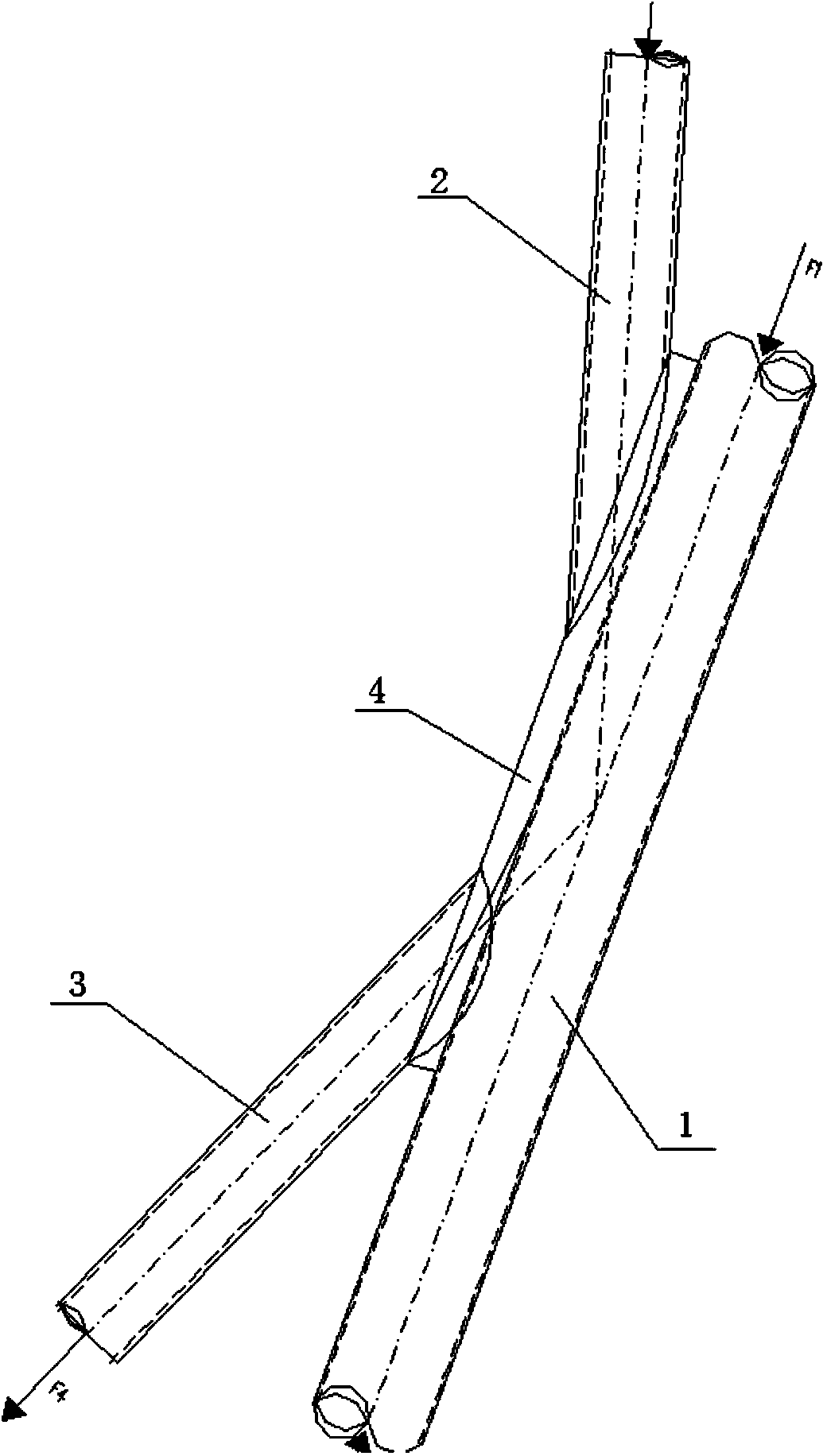
[0052] This embodiment takes the installation of two branch pipes in one main pipe of a flat steel pipe node as an example, such as figure 1 As shown, the steel pipe node provided by the embodiment of the present invention includes: a main pipe 1 , an upper branch pipe 2 , a lower branch pipe 3 , and a backing plate 4 . The backing plate 4 is an arc-shaped plate that fits with the main pipe 1 in an arc. The backing plate 4 covers the main pipe 1 with an arc between 90° and 360°, and can provide welding space for the ends of the upper branch pipe 2 and the lower branch pipe 3. Are 90°, 120°, 150°, 180°, 210°, 240°, 270°, 300°, 330° or 360° curved plates. The upper branch pipe 2 is welded or bolted to the upper edge of the backing plate 4, the lower branch pipe 3 is welded or bolted to the lower edge of the backing plate 4, the backin...


PUM

PropertyMeasurementUnit
angleaaaaaaaaaa
angleaaaaaaaaaa

Abstract

The invention provides a steel tube joint. The steel tube joint comprises a main tube and branch tubes. The axes of the branch tubes intersect with the axis of the main tube. The main tube and the branch tubes are all steel tubes. The steel tube joint is characterized in that a base plate is arranged between the main tube and the branch tubes. Compared with the prior art, the steel tube joint is more reasonable in structural arrangement, overcomes defects of a traditional tubular joint, improves welding conditions of welding joints and obviously improves bearing capacity and stress states.

Description

technical field [0001] The invention relates to a steel pipe node, in particular to a steel pipe node of a steel pipe tower of a transmission line. Background technique [0002] Round steel pipes have unique advantages and are widely used in space truss structures. The connection of steel pipes, that is, node design, is one of the most critical links. Taking the transmission line steel pipe tower as an example, the connection between the steel pipe members of different axes is often in the form of intersecting nodes, that is, the web member is directly welded to the outer surface of the chord, which is often used for the connection of the main inclined material, the inclined material of the tower legs and the tower body. Diaphragm connection and connection of parts such as cross obliques. [0003] The connection between steel pipe members with different axes is often in the form of intersecting nodes, that is, the web member is directly welded to the outer surface of the ch...

Claims


Application Information

Patent Timeline
21 May 2014
Publication
CN103806543A
IPC
E04B1/58
Inventors
胡晓光; 杨靖波