Geared turbine machine

A transmission type and turbine technology, which is applied in the direction of gas turbine devices, machines/engines, mechanical equipment, etc., to achieve the effect of improving the use value and increasing the transmission loss

Inactive Publication Date: 2014-05-21
MAN ENERGY SOLUTIONS SA +1
View PDF6 Cites 9 Cited by
  • Summary
  • Abstract
  • Description
  • Claims
  • Application Information

AI Technical Summary

Problems solved by technology

Limitations are therefore set with regard to the maximum permissible peripheral speed and subsequently also with regard to larger diameters

Method used


Image

  • Geared turbine machine
  • Geared turbine machine

Examples


Embodiment Construction

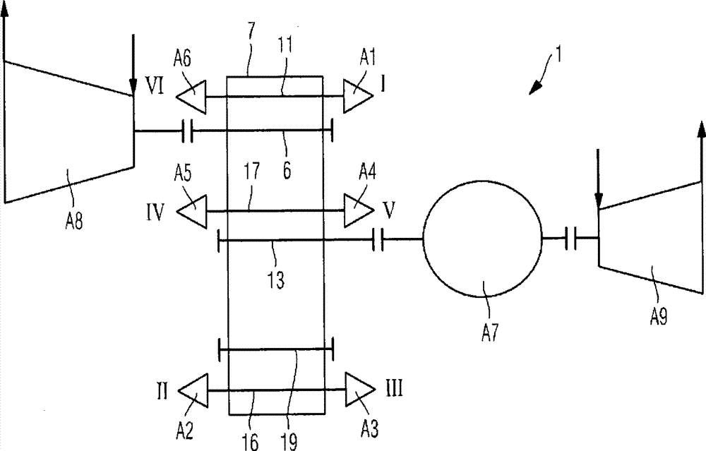
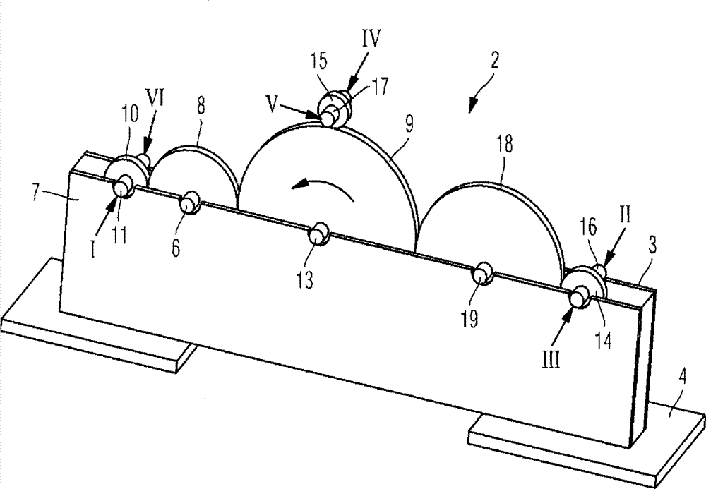
[0058] exist figure 1 The geared turbine shown in is part of a chemical plant for the treatment and reprocessing of gases. This geared turbine (1) integrates the driving and / or driven machinery (A1, A2, A3, A4, A5, A6, A7, A8, A9) into a mechanical transmission line via a transmission mechanism (2), wherein, On the one hand as drive steam turbine, gas turbine, expander and motor, and on the other hand as driven device compressor and generator.

[0059] Individual devices are coupled to each other and assembled in one or more racks (in figure 2 exemplarily shown in the frame (4)). Under the base (4) there is no figure 1 with 2 The coolers, condensers and other devices not essential to the invention but necessary for the operation of the mechanical transmission line are shown in .

[0060] Depending on the overall requirements of the process to be operated (Anforderungsprofil), the motor (A7), the steam turbine (A8) and the expander (A9) can be designed together or individ...


PUM


Abstract

A geared turbine machine integrates driving and/driven devices into mechanical transmission lines through an integrated transmission mechanism, wherein the integrated transmission mechanism comprises a central bull gear with a bull gear shaft, at least two pinions with pinion shafts, and a drive pinion with a drive shaft, wherein the drive pinion is arranged between the bull gear and the first pinion, and meshed with the bull gear, as well as with the first pinion, the bull gear is in operative connection with the second pinion, the bull gear shaft is at least in non-rotatable connection with the driving and/driven devices, the drive shaft of the drive pinion is non-rotationally connected to at least one driving device, and the end portion of the pinion shafts is at least in non-rotatable connection with the driving and/driven devices. The bull gear is so connected to the second pinion in operative connection that between the bull gear and the pinion is arranged with an intermediate idle gear, which is meshed with both the large wheel, as well as with the second pinion.

Description

technical field [0001] The invention relates to a geared turbomachine with the features of the preamble of claim 1 , which integrates a drive and / or output into a mechanical drive train via an integrated transmission. Background technique [0002] Geared turbines are used, for example, for the separation of air in so-called PTA plants (PTA=Purified Terephthalic Acid) for the production of terephthalic acid, wherein here the entire geared turbine is configured as a drive line and Compressors, expanders, steam turbines, motors and generators interact technologically with one another via transmissions. [0003] This results in a pressure increase of the fluid in the compressor, ie, the angular momentum of the fluid from entering the compressor to its outlet is increased by the rotating, radially extending runner wheel of the compressor with blades. The pressure and temperature of the fluid increase in the compressors of this stage, while the relative velocity of the flowing fl...

Claims


Application Information

Patent Timeline
Patent Type & Authority Applications(China)
IPC IPC(8): F01D15/12F01K13/00
CPCF01D15/12F02C7/36F04D25/163
Inventor T·韦德曼H·诺伊贝格尔J-N·布莱尔
Owner MAN ENERGY SOLUTIONS SA
Why Eureka
Try Eureka