Fluid conveying device

A technology of conveying device and fluid, which is applied to the components of pumping device for elastic fluid, liquid variable capacity machinery, pump control, etc. The effect of ensuring service life and working stability

Inactive Publication Date: 2014-05-21
深圳深爱半导体股份有限公司
View PDF5 Cites 1 Cited by
  • Summary
  • Abstract
  • Description
  • Claims
  • Application Information

AI Technical Summary

Problems solved by technology

[0003] Traditional fluid delivery devices mainly use pumps for delivery. Although it is the most convenient, it is difficult for pumps to deliver precise quantitative liquids
[0004] Moreover, after c

Method used


Image

  • Fluid conveying device

Examples


Embodiment Construction

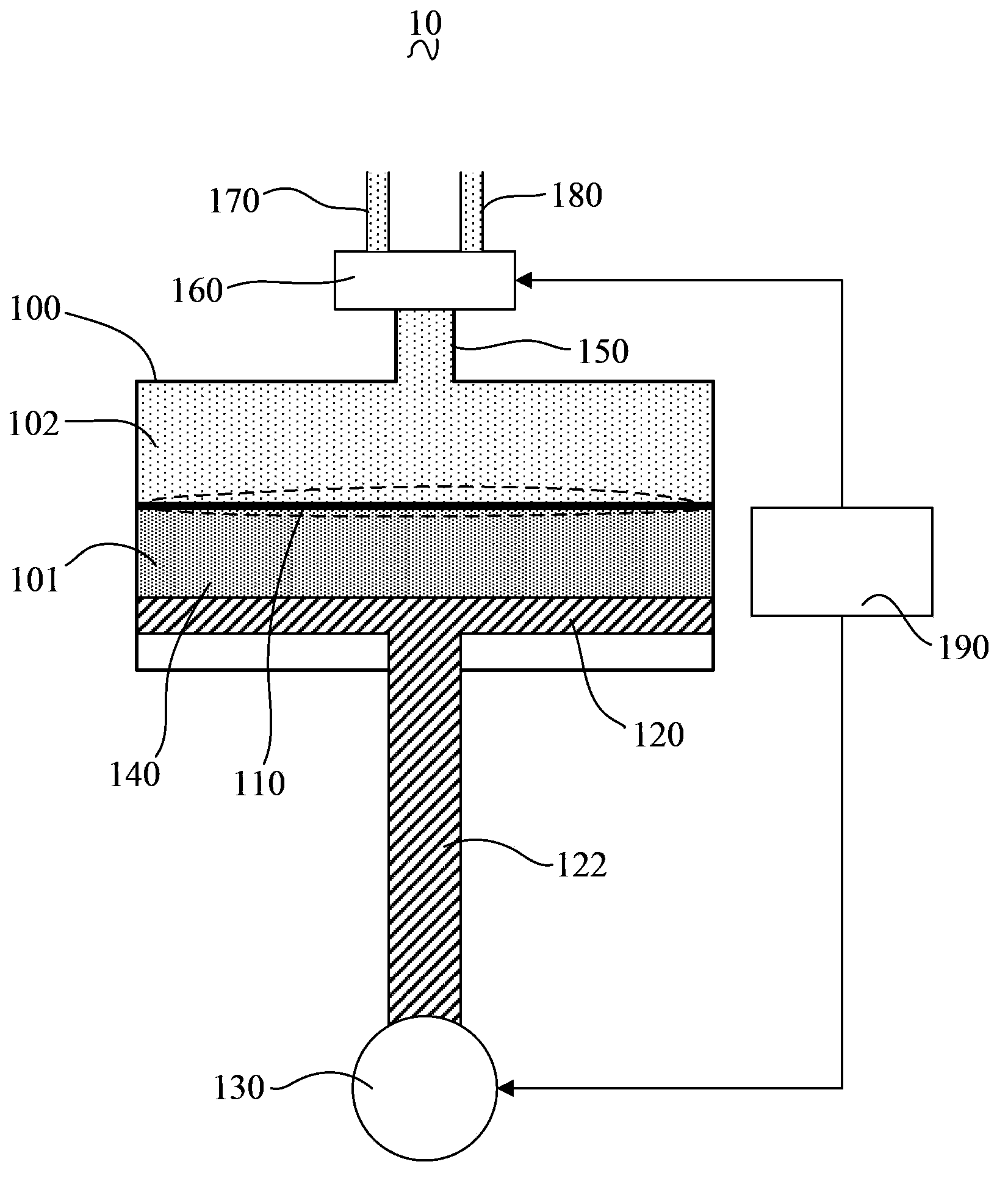
[0029] Such as figure 1 As shown, it is a schematic structural diagram of a fluid delivery device 10 according to an embodiment.

[0030] The fluid delivery device 10 includes: a cylinder 100 , an elastic film 110 , a piston 120 , a connecting rod 122 , a motor 130 , a pump oil 140 , an outlet pipe 150 , an electromagnetic valve 160 , a feed pipe 170 , a discharge pipe 180 and a controller 190 .

[0031] The elastic membrane 110 is located inside the cylinder body 100 and isolates the inner cavity of the cylinder body 100 into two independent first chambers 101 and second chambers 102 .

[0032] In this embodiment, the elastic film 110 is made of Teflon material.

[0033] The piston 120 is located in the first chamber 101 of the cylinder 100 and is in close contact with the inner wall of the first chamber 101 .

[0034] The connecting rod 122 penetrates into the first chamber 101 from the outside and is connected with the piston 120 .

[0035] The motor 130 is connected wit...


PUM


Abstract

The invention discloses a fluid conveying device, which comprises a cylinder block, an elastic film, a piston, a connecting rod, a motor, an outlet pipe, a solenoid valve, a feeding pipe, a discharging pipe and a controller, wherein the elastic film is positioned in the cylinder block; the inner cavity of the cylinder block is isolated into a first cavity and a second cavity which are independent; the piston is positioned in the first cavity of the cylinder block; the connecting rod is penetrated into the first cavity from the outside to be connected with the piston; the motor is connected with the connecting rod and is used for driving the piston to move in the first cavity via the connecting rod; one end of the outlet pipe is communicated with the second cavity of the cylinder block; the other end of the outlet pipe is communicated with the solenoid valve; the feeding pipe and the discharging pipe are respectively communicated with the solenoid valve; the solenoid valve is used for switching the outlet pipe and the feeding pipe to be communicated and switching the outlet pipe and the discharging pipe to be communicated; the controller is connected with the motor and the solenoid valve and is used for controlling the driving of the motor and the switching of the solenoid valve. According to the device, a small quantity of fluid can be more precisely controlled to be conveyed and sucked back by the deformation of the elastic film.

Description

technical field [0001] The invention relates to a fluid delivery device, in particular to a fluid delivery device capable of quantitative delivery. Background technique [0002] In industrial production, liquid substances are often used, such as liquid water and thick glue. Moreover, there is usually a requirement for the demand for the fluid substance, that is, the fluid delivery device is required to be able to provide the fluid substance quantitatively. [0003] Traditional fluid delivery devices mainly use pumps for delivery. Although it is the most convenient, it is difficult for pumps to deliver precise quantitative liquids. [0004] Moreover, after conveying, residual drops are usually generated at the outlet of the fluid material, and the residual drops will drop on the product or parts due to gravity or shaking, resulting in rework or scrapping. Contents of the invention [0005] Based on this, it is necessary to provide a more accurate fluid delivery device tha...

Claims


Application Information

Patent Timeline
IPC IPC(8): F04B43/02F04B49/06F04B53/00
Inventor 节昌喜刘荣兴
Owner 深圳深爱半导体股份有限公司
Why Eureka
Try Eureka