
Systems and methods for guided downshifts

A technology of gears and thresholds, applied in the field of systems and methods for guiding downshifts, and can solve problems such as slowing down, accumulation of condensate, etc.

Active Publication Date: 2016-07-06
FORD GLOBAL TECH LLC
View PDF4 Cites 0 Cited by
  • Summary
  • Abstract
  • Description
  • Claims
  • Application Information

AI Technical Summary

Problems solved by technology

However, the inventors herein have recognized potential problems with these approaches
Specifically, while certain methods can reduce or slow condensate formation in a CAC, condensate can still build up over time

Method used


Image

  • Systems and methods for guided downshifts
  • Systems and methods for guided downshifts
  • Systems and methods for guided downshifts

Examples


Embodiment Construction

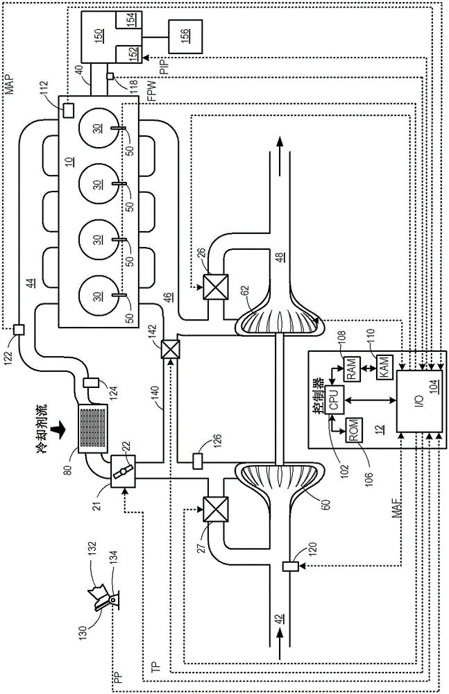
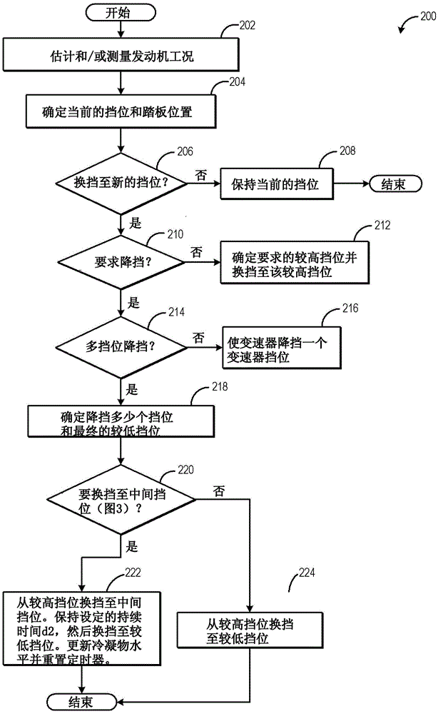
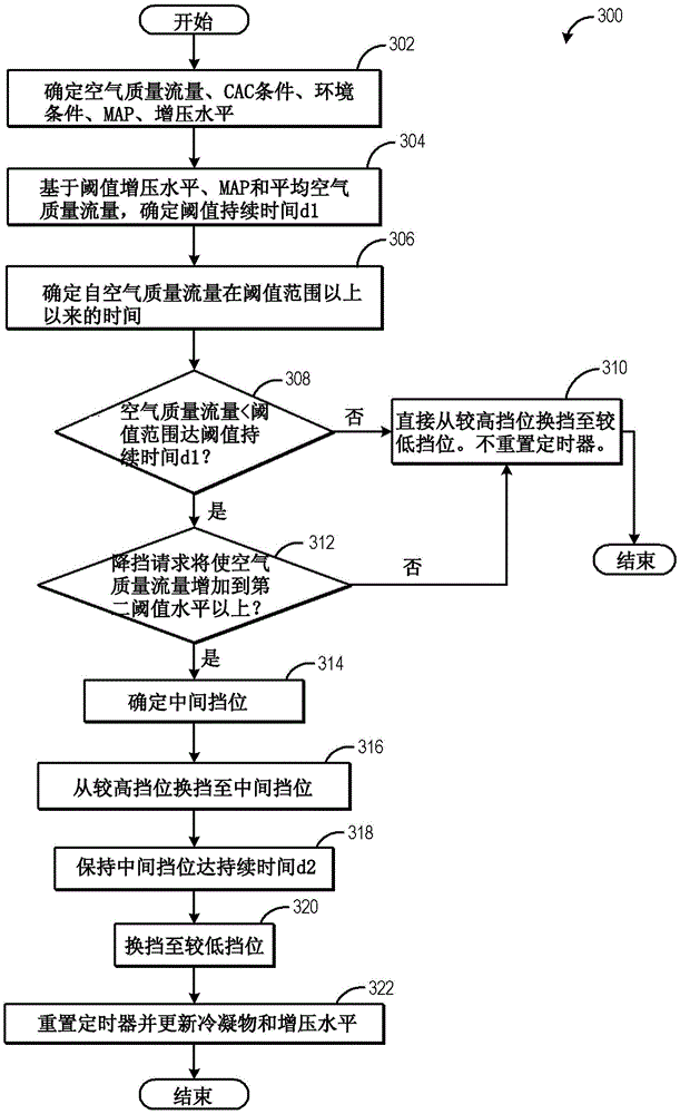
[0022] The following description relates to systems and methods for performing a multi-gear downshift of transmission gears in an engine system, such as figure 1 system. A gear shift request may be generated in response to a change in pedal position. exist figure 2 A method for shifting transmission gears in response to different shift requests is shown in . In response to a request to shift to a new gear, the transmission may upshift to a higher gear, downshift a single gear, or downshift multiple gears. A multi-gear downshift can be performed directly by downshifting from a higher gear to a lower gear, or by temporarily downshifting to an intermediate gear based on factors related to condensate release in the charge air cooler Gears are executed step by step. The controller may, based on engine operating conditions such as air mass flow levels, perform, for example image 3 The control program of the program in order to determine whether the intermediate gear can be us...


PUM


Abstract

The present invention relates to systems and methods for guiding downshifts. Methods and systems are provided for performing a multi-gear downshift of transmission gears by temporarily operating in an intermediate gear. In response to the air mass flow not reaching the threshold set duration of CAC self-cleaning, the transmission gear is downshifted from the higher gear to the intermediate gear and then to the required lower gear. Downshifting through intermediate gears is controlled based on the gear shift request and the maximum air mass flow level at which the engine stalls.

Description

Background technique [0001] Turbocharged engines utilize a charge air cooler (CAC) to cool the compressed air from the turbocharger before it enters the engine. Ambient air from outside the vehicle passes through the CAC to cool intake air passing through the interior of the CAC. Condensation can form in the CAC when the ambient air temperature decreases, or during humid or rainy conditions, where the intake air is cooled below the water dew point. When the intake air contains recirculated exhaust gas, the condensate can become acidic and corrode the CAC casing. This corrosion can lead to leaks between the air charge, the atmosphere, and possibly the coolant in the case of water-cooled air coolers. Condensate can build up in the CAC and then be immediately drawn into the engine during times of increased air mass flow, increasing the chances of the engine stalling. Certain CACs may have a self-cleaning mode that is activated during a threshold level of mass air flow that doe...

Claims


Application Information

Patent Timeline
Patent Type & Authority Patents(China)
IPC IPC(8): F16H59/26F16H59/32
CPCB60W10/11B60W2710/0638F16H2306/14F16H2061/0448F16H59/32F16H2061/0444F16H61/0213F16H2061/2846B60W10/06B60W30/1884F02B29/0468F02D41/0007
Inventor K·R·诺曼S·S·山田
Owner FORD GLOBAL TECH LLC
Learn More