Tool structure for measuring plunger bottom clearance groove depths

A technology for measuring column and head clearance, applied in the direction of mechanical depth measurement, etc., can solve problems such as affecting the processing progress and production efficiency, increasing the cost of human resources, and inaccurate measurement, achieving flexible and convenient adjustment, simple structure, and guaranteed accuracy. Effect

Inactive Publication Date: 2014-05-21
无锡威孚马山油泵油嘴有限公司
View PDF6 Cites 2 Cited by
  • Summary
  • Abstract
  • Description
  • Claims
  • Application Information

AI Technical Summary

Problems solved by technology

At present, according to the requirements of product drawings, the depth of the top clearance groove at the end of the plunger needs to be measured. Due to the mass production of the plunger, the traditional measurement method using measuring tools has the problems of time-consuming, laborious and inaccurate measurement, which not only improves The human resource cost of the enterprise also greatly affects the processing progress and production efficiency

Method used


Image

  • Tool structure for measuring plunger bottom clearance groove depths
  • Tool structure for measuring plunger bottom clearance groove depths
  • Tool structure for measuring plunger bottom clearance groove depths

Examples


Embodiment Construction

[0020] The specific implementation manner of the present invention will be described below in conjunction with the accompanying drawings.

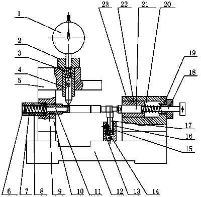
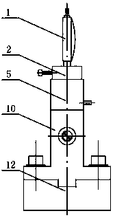
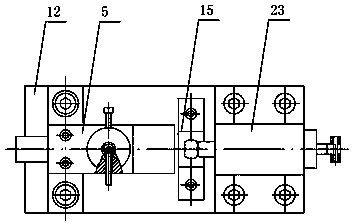
[0021] Such as figure 1 , figure 2 and image 3 As shown, a tooling structure for measuring the depth of the top gap groove of a plunger includes a base 12, including a first assembly unit and a measuring unit arranged perpendicularly to each other, and on the base 12, relative to the first assembly unit, they are arranged at intervals second assembly unit;

[0022] The specific structure of the first assembly unit is as follows:

[0023] Including the male top seat 10, the screw sleeve 8 is screwed to the male top seat 10, one end of the male top bushing 9 extends into the male top seat 10 and abuts against the screw sleeve 8, and the second spring 7 is installed in the screw sleeve 8 , the male tip 11 runs through the male tip bushing 9 and is connected to one end of the second spring 7, the other end of the second spring 7 abuts ag...


PUM


Abstract

The invention relates to a tool structure for measuring plunger bottom clearance groove depths. The tool structure comprises a base, a first assembling unit and a measuring unit, wherein the first assembling unit is perpendicular to the measuring unit. Second assembling units are further arranged on the base relative to the first assembling unit at intervals. The tool structure is simple and convenient to install, the first assembling unit and the second assembling units are utilized to effectively achieve horizontal positioning of plungers, standard positioning of the plungers is achieved by arranging flat position columns, accuracy in plunger bottom clearance groove measurement is guaranteed, and the tool structure is flexible and convenient to adjust and effectively achieves depth measurement of massive plunger bottom clearance grooves of different sizes.

Description

technical field [0001] The invention relates to a tooling structure, in particular to a tooling structure for measuring the depth of a top clearance groove of a plunger. Background technique [0002] The plunger couple is formed by the precision fit of the plunger and the plunger sleeve, and the oil outlet valve couple (composed of the oil outlet valve and the oil outlet valve seat) is installed above it. The plunger can be divided into different types according to the applicable fuel injection pump. Type A, Type B, Type K, Type AD, Type P, etc., to meet the needs of different diesel engines. At present, according to the requirements of product drawings, the depth of the top clearance groove at the end of the plunger needs to be measured. Due to the mass production of the plunger, the traditional measurement method using measuring tools has the problems of time-consuming, laborious and inaccurate measurement, which not only improves The human resource cost of the enterp...

Claims


Application Information

Patent Timeline
IPC IPC(8): G01B5/18
Inventor 缪映映
Owner 无锡威孚马山油泵油嘴有限公司
Why Eureka
Try Eureka