System for determining position of bare chip

A technology for judging systems and bare chips, applied to measuring devices, optical devices, instruments, etc., can solve problems such as low production efficiency, rising costs, and wrong designation of reference chips

Active Publication Date: 2014-05-21
FUJI KK
View PDF9 Cites 11 Cited by
  • Summary
  • Abstract
  • Description
  • Claims
  • Application Information

AI Technical Summary

Problems solved by technology

[0010] However, in the method of using the die adjacent to the notch formed on the edge of the wafer among the plurality of die selected from the dicing sheet as the reference die as in the above-mentioned Patent Document 1, the operator must use Teaching the reference die manually has the disadvantage of low production efficiency
Also, incorrect data

Method used


Image

  • System for determining position of bare chip
  • System for determining position of bare chip
  • System for determining position of bare chip

Examples


Embodiment Construction

[0029] One Example which actualized the form for implementing this invention is demonstrated using drawing.

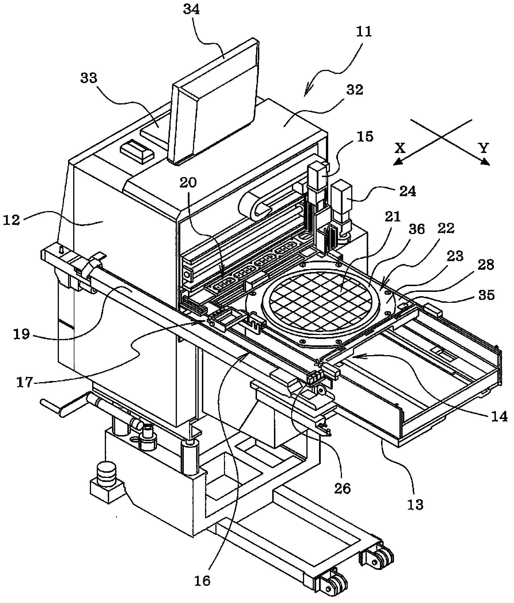
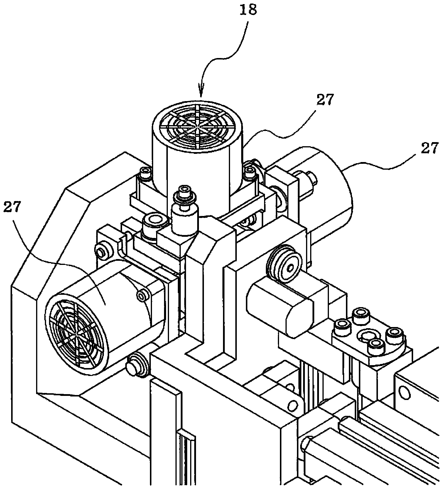
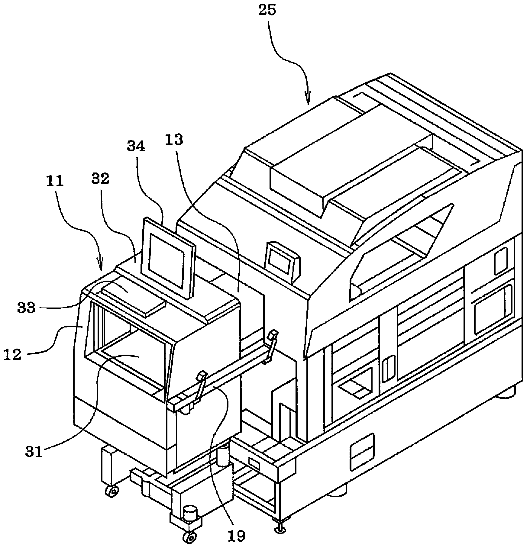
[0030] Such as figure 1 As shown, the die picking device 11 of this embodiment includes: a bin holding part 12 (pan tower), a tray pull-out platform 13, a tray pull-out mechanism 14, an auxiliary manipulator 15, a shuttle mechanism 16, a turning unit 17, and a jacking unit 18 (see figure 2 ), NG conveyor 19, nozzle changer 20, etc. Such as image 3 As shown, this die pickup device 11 is installed in a state where the tray pullout table 13 is inserted into the feeder installation slot of the component mounter 25 .

[0031] Wafer trays on which dies 21 (wafer parts) are placed can be mixed and loaded in multiple stages in a magazine (not shown) that is vertically movable in the magazine holding unit 12 of the die picker 11 22 and a tray tray (not shown) on which tray parts (electronic parts) are placed. Such as Figure 4 and Figure 5 As shown, in the wafer tray ...


PUM


Abstract

The invention provides a system for determining the position of a bare chip by means of determining the position of a bare chip adsorbed by a suction nozzle, and aims to improve the production efficiency and the yield of bare chips. Reference position marks (41) are arranged at two positions on the upper surface of a wafer pallet (22). Bare chip arrangement position information which is generated in a coordinate system of the wafer pallet is stored in a storage unit in advance, and the wafer pallet takes the positions of the reference position marks as the reference. A camera is used to capture the two reference position marks on the wafer pallet at the specified positions of a bare chip pick device, a shot picture is processed to identify the two reference position marks in a mechanical coordinate system of the bare chip pick device, the positional deviation value between the coordinate system of the wafer pallet and the mechanism coordinate system of the bare chip pick device is calculated, and the bare chip arrangement position information is corrected according to the positional deviation value, and thus the arrangement positions of various bare chips (21) in the mechanical coordinate system of the bare chip pick device are obtained.

Description

technical field [0001] The utility model relates to a bare chip position judging system for judging the position of a bare chip sucked by a suction nozzle. Background technique [0002] For example, as described in Patent Document 1 (Japanese Unexamined Patent Application Publication No. 2006-332417 ), a wafer tray on which stretchable dicing sheets are spread, on which wafers cut in a checkerboard pattern are pasted, is set on a die picker, When using the suction nozzle to pick up the die separated from the wafer on the dicing sheet, lift the sticking part of the die to be adsorbed in the dicing sheet from directly below it with a jacking bottle (die ejector) The sticking part of the die is partially peeled off from the dicing sheet, and at the same time, the die is picked up from the dicing sheet by sucking the die with a suction nozzle. [0003] In this die pickup device, it is necessary to align the suction nozzle with the die every time the die is picked up. Therefore,...

Claims


Application Information

Patent Timeline
IPC IPC(8): G01B11/00H01L21/67
Inventor 柴田光彦
Owner FUJI KK
Why Eureka
Try Eureka