Arrangement method of WAT (wafer acceptance test) head

A layout method and technology of test heads, which are applied in the direction of measuring devices, measuring electrical variables, instruments, etc., to achieve the effect of saving floor space

Active Publication Date: 2014-05-21
SHANGHAI HUALI MICROELECTRONICS CORP
View PDF7 Cites 2 Cited by
  • Summary
  • Abstract
  • Description
  • Claims
  • Application Information

AI Technical Summary

Problems solved by technology

However, this invention does not provide a technical solution for the

Method used


Image

  • Arrangement method of WAT (wafer acceptance test) head
  • Arrangement method of WAT (wafer acceptance test) head
  • Arrangement method of WAT (wafer acceptance test) head

Examples


Embodiment Construction

[0012] The present invention will be further described below in conjunction with the accompanying drawings and specific embodiments, but not as a limitation of the present invention.

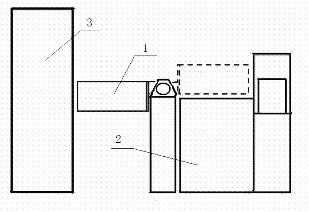
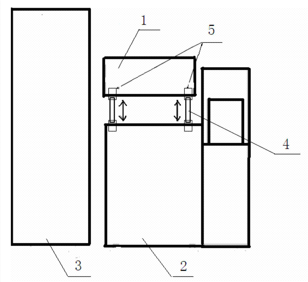
[0013] Such as Figure 1 to Figure 5 Shown, a kind of arrangement method of WAT test head, wherein, comprise: hydraulic drive device 5, described hydraulic drive device 5 comprises four hydraulically driven elevating rods 4, fixes described four on the upper surface of probe machine table 2 Hydraulically driven lifting rods 4, the four hydraulically driven lifting rods 4 are respectively fixedly connected to the four corners of the bottom surface of the test head 1; a control device (not marked in the drawings) is also provided, and the control device It is electrically connected with the hydraulic drive device 5 .

[0014] The WAT machine includes a test machine 3 and a Prober probe machine 2. Add four hydraulic transmission devices 5 to the probe machine 2 (Prober machine) and connect it to t...


PUM


Abstract

The invention discloses an arrangement method of a WAT head. The method comprises a hydraulic driving device and a control device, wherein the hydraulic driving device comprises four hydraulic driving lifting rods, the upper surface of a probe machine table is fixedly provided with the four hydraulic driving lifting rods, and the four hydraulic driving lifting rods are fixedly connected to the four corners of the bottom surface of the test head; the control device is electrically connected with the hydraulic driving device. When the test head is maintained, a rotating type scheme is replaced by a test head lifting type scheme, so that space occupation can be reduced.

Description

technical field [0001] The invention relates to the field of semiconductor testing, in particular to a novel method for arranging WAT test heads. Background technique [0002] Such as figure 1 The WAT machine shown is acceptable for the current (WAT) wafer test. The machine is composed of Tester (test machine) and Prober (probe machine). The Tester is divided into cabinets and test heads: normal state machine The platform covers an area of ​​about 6m^2. The test head is a reversible structure, driven by the hub of the Prober, and can be rotated 180 degrees through the rotation axis: when the equipment or manufacturer is doing maintenance work on the test head part, it will be necessary to turn the test head 180 degrees to test The head part should be repaired accordingly. However, after being turned over, it will take up more ground space in the horizontal direction, and the extra floor area will be about 9m^2, which is 50% more floor area. As the demand for production c...

Claims


Application Information

Patent Timeline
IPC IPC(8): G01R35/00
Inventor 王靓莫保章
Owner SHANGHAI HUALI MICROELECTRONICS CORP
Why Eureka
Try Eureka