RFID card reader

A card reader and card reading technology, which is applied in the field of signal sources, can solve the problems of inability to transmit data and the use of RFID card readers is not convenient enough, and achieve the effects of simple networking, omitting wiring, and improving performance.

Inactive Publication Date: 2014-05-21
姜韫英
View PDF0 Cites 2 Cited by
  • Summary
  • Abstract
  • Description
  • Claims
  • Application Information

AI Technical Summary

Problems solved by technology

[0004]The existing RFID card reader is not convenient to use

Method used


Image

  • RFID card reader

Examples


Example Embodiment

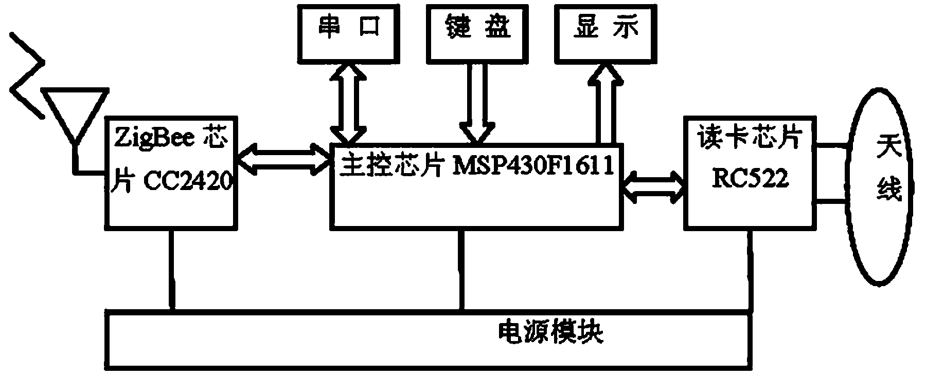
[0013] As shown in the figure, the present invention includes a ZigBee chip, a main control chip, a power module, a keyboard, a card reader chip, and an antenna. The main control chip is respectively connected to the ZigBee chip, power module, keyboard, and card reader chip, and the card reader chip is connected to the antenna.

[0014] The ZigBee chip uses CC2420.

[0015] The main control chip adopts MSP430F1611.

[0016] The design of the antenna circuit of the present invention: the antenna interface includes: VMID (pin 16), TX1 (pin 11), TX2 (pin 13), RX (pin 17). The signal transmitted from the TX1 and TX2 pins is a modulated 13.56 MHz carrier signal, supplemented by multiple passive components to achieve matching and filtering functions to directly drive the antenna. The internal receiving circuit uses the card's response signal to have the function of modulation on the double-sideband of the subcarrier. Use the VMID signal generated inside MFRC522 as the bias of the RX ...


PUM


Abstract

An RFID card reader belongs to the technical field of a signal source. The invention especially relates to an RFID card reader and provides an RFID card reader which can transmit data through a network at any time. The RFID card reader comprises a ZigBee chip, a main control chip, a power supply module, a keyboard, a card reading chip and an antenna. The main points of the structure are that the main control chip is respectively connected with the ZigBee chip, the power supply module, the keyboard and the card reading chip, and the card reading chip is connected with the antenna.

Description

Technical field [0001] The invention is a signal source technology field, especially involving an RFID card reader. Background technique [0002] In recent years, the application of RFID technology has developed rapidly.Because RFID technology can bring great convenience to people, with the decline in prices and the improvement of the technology itself, the field of RFID applications is more extensive, such as public safety, production management, logistics management, traffic management and other fields.Although RFID technology has developed a certain degree, there are still many shortcomings in large -scale applications.One of them is a wired connection between the card reader and the server. The position of the card reader is fixed. Under the urgent need, it cannot temporarily and quickly transmit data to the server to meet the short -term and fast application needs. [0003] ZigBee technology is a close -range wireless network communication technology with low power consumpti...

Claims


Application Information

Patent Timeline
IPC IPC(8): G06K7/00
Inventor 姜韫英蒋国敬
Owner 姜韫英
Why Eureka
Try Eureka