Rotor And Brushless Motor

A technology of brushless motors and rotors, which is applied in the manufacture of motor generators, electric components, synchronous motors with stationary armatures and rotating magnets, etc., and can solve problems such as easy demagnetization of excitation magnets

Active Publication Date: 2014-05-21
DENSO CORP
View PDF10 Cites 6 Cited by
  • Summary
  • Abstract
  • Description
  • Claims
  • Application Information

AI Technical Summary

Problems solved by technology

Therefore, the field magnet is easily affected by external influences. For example, there is a problem that the field magnet is easily demagnetized (irreversible temperature change) when the temperature in the engine room of the vehicle becomes high.

Method used


Image

  • Rotor And Brushless Motor
  • Rotor And Brushless Motor
  • Rotor And Brushless Motor

Examples


Embodiment Construction

[0077] Below, according to figure 1 and figure 2 A first embodiment of the brushless motor will be described.

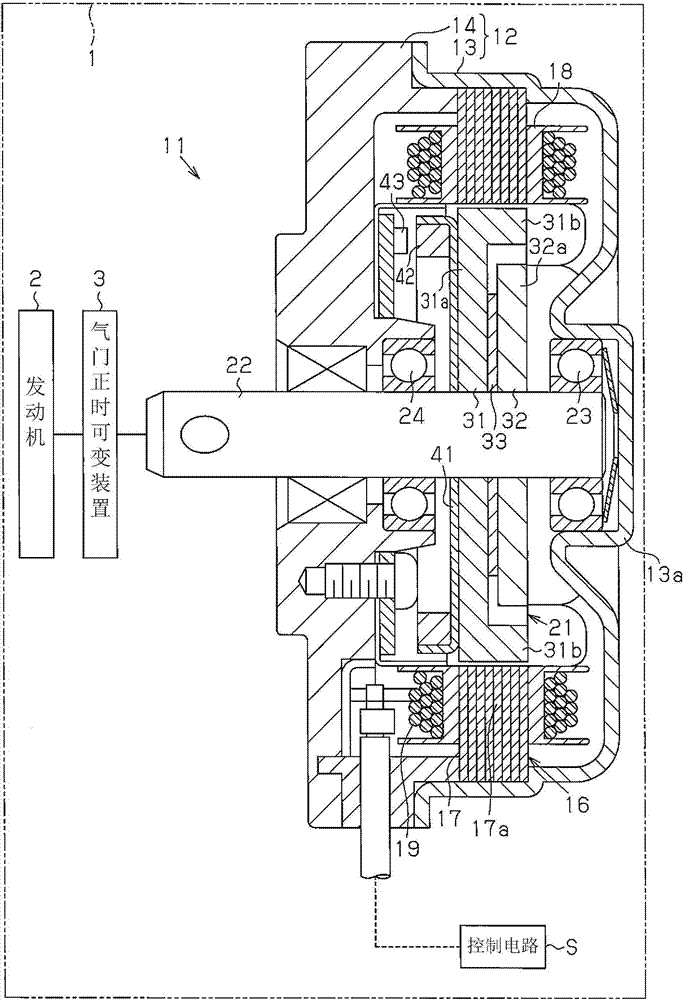
[0078] Such as figure 1 As shown, the brushless motor 11 of this embodiment is used in a position control device arranged in a vehicle engine compartment 1 , more specifically, in a variable valve timing device 3 connected to an engine 2 .

[0079] Such as figure 1 As shown, the motor case 12 of the brushless motor 11 has a bottomed cylindrical casing 13 and the front side of the cylindrical casing 13 ( figure 1 The front end plate 14 with the opening closed in the center and left side).

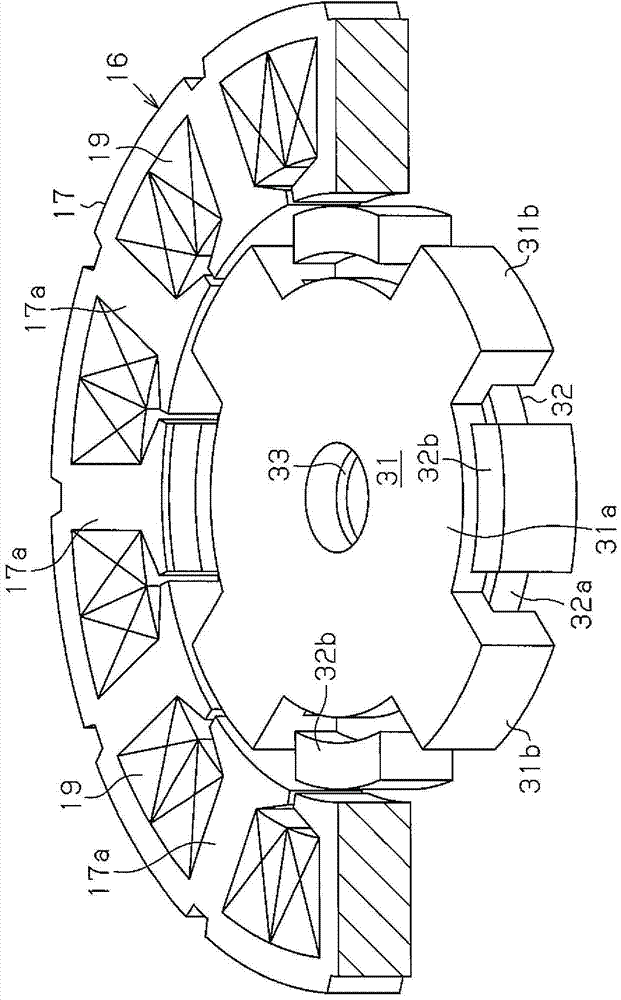
[0080] Such as figure 1 As shown, a stator 16 is fixed to the inner peripheral surface of the cylindrical housing 13 . The stator 16 includes: an armature core 17 having a plurality of (twelve in this embodiment) teeth 17a extending radially inward as concentrated winding teeth; and a winding 19 wound around the armature core 17 via an insulator 18 On the tooth 17a. The st...


PUM


Abstract

A rotor includes a first rotor core, a second rotor core, a field magnet, and a detected portion. The first rotor core includes a first core base and a plurality of first claw-shaped magnetic pole portions. The second rotor core includes a second core base and a plurality of second claw-shaped magnetic pole portions. The first and second core bases face to each other, and the first and second claw-shaped magnetic pole portions are alternately arranged in the circumferential direction. The field magnet is located between the first and second core bases in the axial direction. The field magnet has the first claw-shaped magnetic pole portion function as a first magnetic pole and has the second claw-shaped magnetic pole portion function as a second magnetic pole. A detected portion, which generates a magnetic flux, is arranged at an outer axial end surface of the first rotor core.

Description

technical field [0001] The invention relates to a brushless motor and a rotor. Background technique [0002] Conventionally, as an electric motor used in a position control device disposed in an engine room of a vehicle, there has been, for example, a brushless motor used in a variable valve timing device disclosed in Japanese Patent No. 4468033 . This brushless motor has a rotor including a rotor core and a field magnet. The rotor core has a hole penetrating in the axial direction, and the field magnet is inserted and fixed into the hole. [0003] However, in the brushless motor as described above, the field magnet is inserted and fixed into a hole penetrating in the axial direction of the rotor core. Therefore, the field magnet is easily affected by external influences. For example, there is a problem that the field magnet is easily demagnetized (irreversible temperature change) when the engine room of the vehicle becomes high temperature. In addition, since the magnetic...

Claims


Application Information

Patent Timeline
Patent Type & Authority Applications(China)
IPC IPC(8): H02K1/22
CPCH02K21/16H02K1/2713H02K1/28H02K15/03H02K2213/03H02K1/27H02K1/243H02K15/022H02K21/044
Inventor 山田洋次三上晃司森田智惠土屋贵宏横山诚也铃木隆由
Owner DENSO CORP
Why Eureka
Try Eureka