Permanent magnet coupler limiting structure

A technology of permanent magnetic coupler and limit structure, which is applied in the direction of electrical components, electromechanical devices, electromechanical transmission devices, etc. It can solve the problems of large energy transmission loss, inconvenient on-site maintenance, and reduced transmission performance, so as to achieve the effect of improving the service life

Active Publication Date: 2014-05-21
山东东朋自控仪表有限公司
View PDF1 Cites 5 Cited by
  • Summary
  • Abstract
  • Description
  • Claims
  • Application Information

AI Technical Summary

Problems solved by technology

However, in actual operation, the axial movement from the motor end or load end is inevitable, especially the shaft movement of the motor will reach the maximum within a few seconds after starting up, and due to the The speed gap between them is the largest, if there is mechanical friction between the two, it will immediately cause damage to the permanent disk due to friction and heat or reduce the transmission performance
If the air gap between the conductor disk and the permanent disk is set too large for this purpose, although friction can be avoided, the loss of energy transmission will be large, which is also a very undesirable solution
At present, equipment damage caused by this is relatively frequent, and on-site maintenance is very inconvenient, and may cause greater losses due to production stoppage, and sending such large equipment back to the factory for maintenance will delay its use.

Method used


Image

  • Permanent magnet coupler limiting structure
  • Permanent magnet coupler limiting structure
  • Permanent magnet coupler limiting structure

Examples


Embodiment Construction

[0015] The principles and features of the present invention are described below in conjunction with the accompanying drawings, and the examples given are only used to explain the present invention, and are not intended to limit the scope of the present invention.

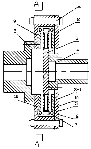
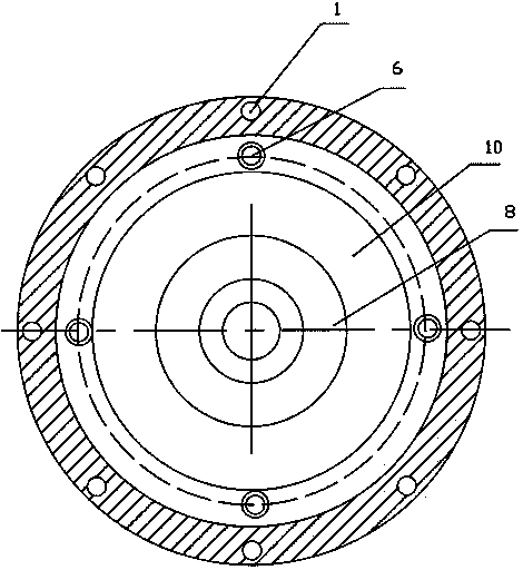
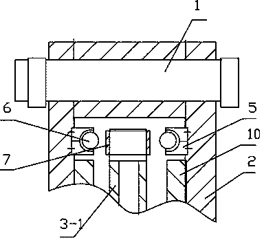
[0016] Such as Figure 1 to Figure 3 As shown, a limiting structure of a permanent magnetic coupler includes a conductor rotor disk and a permanent magnet rotor disk 3, and the conductor rotor disk includes a driving side conductor disk 9 and a driven side conductor disk 2 fixedly connected by bolts 1. The permanent magnet rotor disk 3 is arranged between the two conductor disks, the permanent magnet rotor disk 3 is provided with a permanent magnet 3-1, and the conductor rotor disk is also provided with a conductor plate 10, on the permanent magnet 3-1 There is a fixed air gap between the conductor plate 10, which is characterized in that the inside of the active side conductor plate 9 and the driven side conductor ...


PUM


Abstract

The invention relates to a permanent magnet coupler limiting structure which comprises a conductor rotor disc and a permanent magnet rotor disc. The conductor rotor disc comprises a driving side conductor disc and a driven side conductor disc which are fixedly connected through a bolt, the permanent magnet rotor disc is arranged between the two conductor discs and provided with a permanent magnet, the conductor rotor disc is provided with a conductor plate, and a fixed air gap is reserved between the permanent magnet and the conductor plate. The permanent magnet coupler limiting structure is characterized in that limiting blocks are symmetrically arranged on the inner side of the driving side conductor disc and the inner side of the driven side conductor disc, roll balls are embedded on the limiting blocks in a rolling mode, limiting slideways are arranged at the positions of two sides of the permanent magnet rotor disc corresponding to the limiting blocks, fixed intervals are reserved between the limiting slideways and the roll balls, and the fixed air gap is larger than the fixed intervals. The limiting blocks are provided with spherical grooves, and the roll balls are embedded in the spherical grooves. The permanent magnet coupler limiting structure has the advantage that direct mechanical friction between the conductor discs and a permanent magnet disc is avoided.

Description

technical field [0001] The invention relates to the technical field of magnetic force couplers, in particular to a limiting structure of a permanent magnetic coupler. Background technique [0002] Fixed moment type magnetic coupling realizes the torque transmission from the motor to the load through the air gap between the conductor disk and the permanent disk. Due to its high reliability, simple equipment structure and low failure rate, it is widely used in mines and factory. In order to ensure a higher transmission efficiency, the air gap between the conductor disk and the permanent disk should be smaller in theory, but in fact, due to processing and assembly technology reasons, a certain air gap must generally be guaranteed to avoid Mechanical friction occurs during operation. For couplers with higher power, such as large fan loads used in mines, due to consideration of axial displacement during high-speed rotation, the air gap should generally be reserved at 5 to 8 mm....

Claims


Application Information

Patent Timeline
Patent Type & Authority Applications(China)
IPC IPC(8): H02K51/00
Inventor 李建朋刘锋梁春海
Owner 山东东朋自控仪表有限公司
Why Eureka
Try Eureka