
Magnetic suspension water turbine-generator set

A generator set and maglev technology, applied in hydropower, engine components, machines/engines, etc., can solve the problems of high production cost, operation and maintenance cost, heavy workload, etc., to reduce operation and maintenance cost, improve efficiency of motor, avoid The effect of mechanical friction

Pending Publication Date: 2017-05-10
重庆宙盾新能源技术开发有限公司
View PDF8 Cites 2 Cited by
  • Summary
  • Abstract
  • Description
  • Claims
  • Application Information

AI Technical Summary

Problems solved by technology

[0002] Many years ago, water wheels were used in China for lifting irrigation and grain processing, etc.; most of modern water turbines are installed in hydropower stations to drive generators to generate electricity, and now a relatively mature hydropower technology has been formed; in large and medium-sized hydropower The unit basically adopts a vertical shaft structure. The runner of the vertical hydroelectric generator set and the rotor of the generator are connected together through the main shaft. The weight of the rotating part is transmitted to the machine base through the main shaft and thrust bearing, and then to the foundation; The rotating part of the turbine generator set is very heavy. The traditional load-bearing method mainly uses thrust bearings. The thrust bearing bears the weight of the rotating part of the entire unit and the water thrust in the axial direction of the turbine. There are problems of mechanical friction and mechanical aging; especially in the long-term heavy load state. The mechanical wear and heating problems caused by the friction under the environment are very prominent. For this reason, there are very strict requirements on the load-bearing bearings in the load-bearing system of large hydro-generator sets. In order to solve these problems, each power plant has to arrange regular maintenance, minor repairs, overhauls and Temporary defect treatment, the workload of each bearing repair in these repairs is the largest, so the production cost and operation and maintenance cost are high

Method used


Image

  • Magnetic suspension water turbine-generator set
  • Magnetic suspension water turbine-generator set
  • Magnetic suspension water turbine-generator set

Examples


Embodiment Construction

[0028] Hereinafter, the preferred embodiments of the present invention will be described in detail with reference to the accompanying drawings.

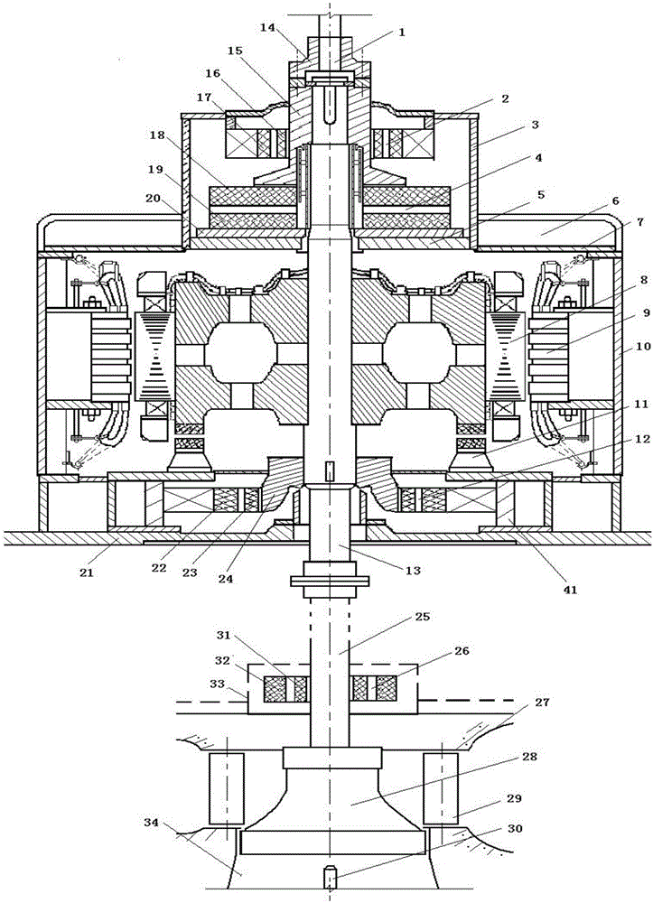
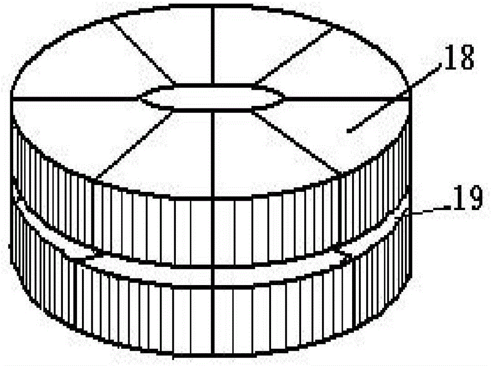
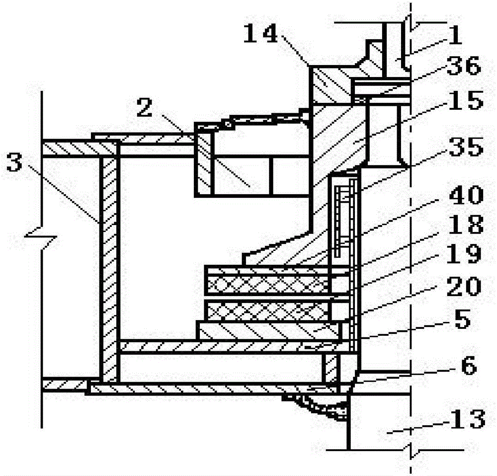
[0029] Such as figure 1 Shown is a schematic diagram of the structure of the magnetic levitation water turbine generator set of the present invention; figure 2 Shown are the structural schematic diagrams of the upper and lower bushes of the thrust bearing in the magnetic levitation water turbine generator set of the present invention; a magnetic levitation hydraulic turbine generator set of the present invention includes a water turbine, a generator installed above the water turbine, an exciter and a magnetic levitation mechanism;

[0030] The generator includes a generator lower support 21, a generator housing 10 fixed on the generator lower support 21, and a generator upper support 6 fixed on the generator housing 10, and the generator housing 10 is provided with The generator shaft 13, the generator rotor 8 and the generator stator 9 a...


PUM


Abstract

The invention discloses a magnetic suspension water turbine-generator set, comprising a water turbine, a generator installed on the water turbine, an exciter and a magnetic suspension mechanism, wherein the water turbine comprises a water turbine volute, a water turbine top cover, water turbine guide vanes, a water turbine shaft and a water turbine rotor, and the water turbine shaft is fixedly connected with a generator shaft; the magnetic suspension mechanism comprises a magnetic suspension upper guide positioning bearing sleeving on a thrust collar, a magnetic suspension lower guide positioning bearing sleeving the lower end of the generator shaft, a magnetic suspension thrust bearing sleeving the generator shaft and a magnetic suspension water turbine positioning bearing sleeving the water turbine shaft. By arranging the magnetic suspension thrust bearing, the magnetic suspension upper guide positioning bearing and the magnetic suspension lower guide positioning bearing, the rotating part of the water turbine-generator set is suspended in air, the water turbine-generator set runs without any mechanical friction, mechanical friction of the bearings is avoided, the efficiency of the generator set is improved, the production cost and the operation and maintenance cost are reduced, and the economic benefit is improved.

Description

Technical field [0001] The invention belongs to the technical field of generators, and specifically relates to a magnetic levitation hydraulic generator set. Background technique [0002] Many years ago, China adopted water wheels for irrigation and grain processing; modern water turbines are mostly installed in hydropower stations to drive generators to generate electricity. Nowadays, a relatively mature hydropower technology has been formed; in large and medium hydropower generation The unit basically adopts a vertical shaft structure. The runner and the generator rotor of the vertical turbine generator set are connected together by the main shaft. The weight of the rotating part is transmitted to the base through the main shaft and thrust bearing, and then transmitted to the foundation; The rotating part of the turbo-generator set is heavy. The traditional load-bearing method mainly uses thrust bearings. The thrust bearing bears the weight of the rotating parts of the whole se...

Claims


Application Information

Patent Timeline
IPC IPC(8): F03B11/06F03B11/00F03B13/00
CPCF03B11/008F03B11/06F03B13/00Y02E10/20
Inventor 向志贤
Owner 重庆宙盾新能源技术开发有限公司
Learn More