Water blocking method used in water blocking system of model aircraft

A technology of blocking water and model aircraft, applied in the direction of ships, etc., can solve the problems of hindering the power output of the electric motor, damaging the electric motor, insufficient power of the model, etc., and achieving the effect of improving the comprehensive performance and reducing the friction force.

Inactive Publication Date: 2015-09-23
CHONGQING UNIV
View PDF9 Cites 0 Cited by
  • Summary
  • Abstract
  • Description
  • Claims
  • Application Information

AI Technical Summary

Problems solved by technology

In this way, relying on the sealing effect of the rubber skin to achieve the effect of water blocking, but this method makes the propeller shaft and the rubber skin have a large friction force, which hinders the power output of the electric motor with a small power, which not only makes the model Insufficient power, long-term use will damage the electric motor, and the effect will not be good after the rubber ages

Method used


Image

  • Water blocking method used in water blocking system of model aircraft
  • Water blocking method used in water blocking system of model aircraft
  • Water blocking method used in water blocking system of model aircraft

Examples


Embodiment 1

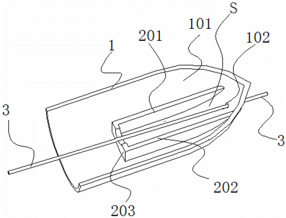
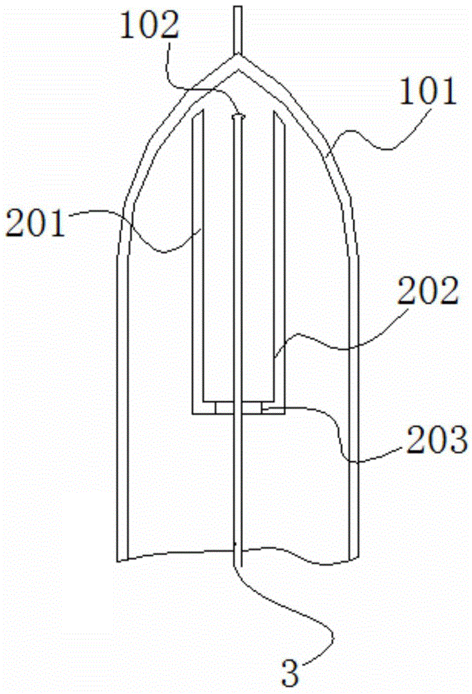
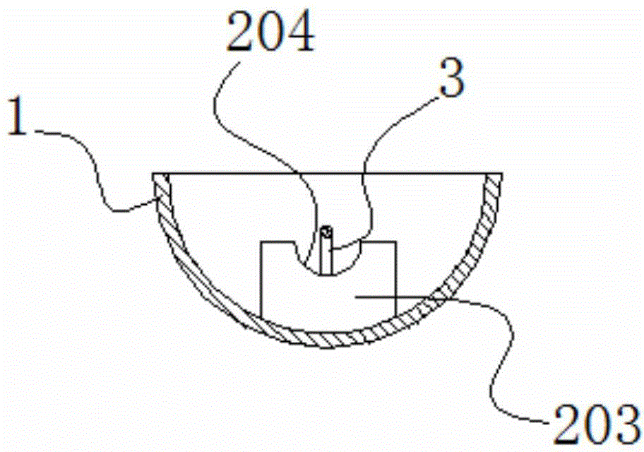
[0029] This embodiment discloses a water blocking method for an airplane model, which includes a model airplane hull 1, a propeller shaft 3, and a first longitudinal rib 201, a second longitudinal rib 202, and a transverse rib 203 installed inside the airplane model hull 1. Aeromodelling water blocking system.

[0030] The stern 101 of the model airplane hull 1 is provided with a propeller water inlet hole 102 . One end of the propeller shaft 3 is connected to the electric motor, and the other end passes through the propeller water inlet 102, and then the propeller is installed. see figure 1 Or 4, the propeller shaft 3 is obliquely inserted into the propeller water inlet hole 102, and the end of the propeller shaft 3 connected to the electric motor is higher than the position of the propeller water inlet hole 102. It is worth noting that, in most aircraft models, the propeller shaft 3 is connected with the output shaft of the electric motor through a rubber sleeve.

[0031]...

Embodiment 2

[0039] This embodiment discloses a water blocking method for an airplane model, which includes a model airplane hull 1, a propeller shaft 3, and a first longitudinal rib 201, a second longitudinal rib 202, and a transverse rib 203 installed inside the airplane model hull 1. Aeromodelling water blocking system.

[0040] The stern 101 of the model airplane hull 1 is provided with a propeller water inlet hole 102 . One end of the propeller shaft 3 is connected to the electric motor, and the other end passes through the propeller water inlet 102, and then the propeller is installed. see figure 1Or 4, the propeller shaft 3 is obliquely inserted into the propeller water inlet hole 102, and the end of the propeller shaft 3 connected to the electric motor is higher than the position of the propeller water inlet hole 102. It is worth noting that, in most aircraft models, the propeller shaft 3 is connected with the output shaft of the electric motor through a rubber sleeve. In this e...


PUM


Abstract

The invention aims to provide a technical scheme for solving the problem that a model boat is leaked on the premises of not influencing the power of the model boat and not influencing water around the model boat, namely a model boat water resistant system and a model boat water resistant method. The model boat water resistant system comprises a model boat body, a propeller shaft, and a first longitudinal rib plate, a second longitudinal rib plate and a horizontal rib plate which are arranged inside the model boat body. The model boat water resistant method comprises the following steps of melting paraffin in a crucible; adding powdered graphite into the crucible, and stirring a mixture consisting of the powdered graphite and the molten paraffin; starting a motor of the model boat to make the propeller shaft rotate; pouring the mixture into an area enclosed by the first longitudinal rib plate, the second longitudinal rib plate and the horizontal rib plate; after the mixture is solidified, closing the motor.

Description

technical field [0001] The invention relates to the technical field of nautical model making. Background technique [0002] Aircraft model is the abbreviation of nautical model, which refers to the model of ships and warships, and also refers to the model making, competition, exhibition and performance in sports events. It is a scientific and technological, military, sports, cultural and educational activity. Through various forms such as making models, competitions, exhibitions, and performances, learn about various knowledge about ships, navy, and oceans, and improve the overall quality of young people. The nautical model competition has been carried out in my country for more than 40 years and is loved by the masses, especially young people. [0003] Most sailing models are powered by electric motors. The electric motor is usually connected to a propeller shaft that enters the water, and the propeller is installed at the water entry end of the propeller shaft. Rely o...

Claims


Application Information

Patent Timeline
Patent Type & Authority Patents(China)
IPC IPC(8): A63H23/02
Inventor 康悦刘溢包安泽马睿宸曹悦翔朱诚王丽娟郝志岩
Owner CHONGQING UNIV
Why Eureka
Try Eureka