Pneumatic quick swing type workpiece transfer device

A pneumatic and fast technology, applied in the direction of conveyor objects, transportation and packaging, which can solve problems such as accelerated wear of hinge points, limited rotation speed of four-bar linkage, structural damage, etc.

Inactive Publication Date: 2014-05-28
CHONGQING FENGGUO QIYANG TECH DEV
View PDF0 Cites 7 Cited by
  • Summary
  • Abstract
  • Description
  • Claims
  • Application Information

AI Technical Summary

Problems solved by technology

Usually a four-bar linkage mechanism is used to achieve the above functions. However, since the rotation speed of the four-bar linkage mechanism is limited, and the rods are often hinged, once the speed is too high, the wear of the hinge point will be accelerated, and then cause structural damage
Therefore, subject to the above structure, the transportation efficiency of workpieces cannot be effectively improved

Method used


Image

  • Pneumatic quick swing type workpiece transfer device

Examples


Embodiment Construction

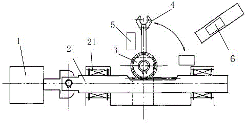
[0011] like figure 1 As shown, the electromagnetic fast swing back device of the present invention, the cylinder 1 and the support, and the cylinder 1 and a rack 2 are riveted together. The tooth bar 2 is fixed on the support by the guide bearing 21, and a gear 3 is meshed on the tooth bar 2, and the rotating shaft of the gear 3 is hinged on the support, and the bar head of the jaw 4 is fixed on the gear 3.

[0012] When in use, due to the use of the cylinder 1 as the power device, the expansion and contraction of the piston rod of the cylinder 1 drives the rack 2 to move back and forth on the support, because a gear 3 is engaged on the rack 2, and the rotating shaft of the gear 3 is hinged on the support. In this way, driven by the reciprocating motion of the rack 2, the fixed jaw 4 on the gear 3 will swing around the gear 3, and can freely move between the feeding position of the workpiece 5 and the discharging position of the workpiece 5. swing. Moreover, the expansion an...


PUM


Abstract

The invention provides a pneumatic quick swing type workpiece transfer device comprising a cylinder and a support seat. The cylinder is fixed on the support seat. A piston rod of the cylinder is fixedly connected to a horizontal rack which is fixed on the support seat through two guide bearings. The middle tooth face of the rack is engaged with a gear, the rotary shaft of the gear is hinged to the support seat, and a jaw is fixed on the gear. Since the cylinder is adopted as a power device, stretching of the piston rod of the cylinder drives the rack to perform reciprocating movement on the support seat; since the gear is engaged with the rack, and the rotary shaft of the gear is hinged to the support seat, by means of driving of the reciprocating movement of the rack, the jaw fixed on the gear swings around the gear freely between a workpiece feeding position and a workpiece discharging position. The stretch range of the cylinder piston rod can be adjusted freely, and accordingly the swing range of the jaw can be adjusted by adjusting the cylinder to meet the using requirements.

Description

technical field [0001] The invention relates to a material transfer device, in particular to a pneumatic fast swing back type workpiece transfer device. Background technique [0002] In mechanical automatic processing, it is often necessary to automatically drive and clamp workpieces, and transfer workpieces in various processing paths to achieve the purpose of classified processing. However, when the feed port and discharge port of the workpiece to be transferred differ by a rotation angle, the clamping jaws are required to drive the workpiece to rotate by an angle after clamping the workpiece, so as to send the workpiece to the next processing position. Usually a four-bar linkage mechanism is used to achieve the above functions. However, since the rotation speed of the four-bar linkage mechanism is limited, and the rods are often hinged, once the speed is too high, the wear of the hinge point will be accelerated, and then cause structural damage. Therefore, limited by th...

Claims


Application Information

Patent Timeline
Patent Type & Authority Applications(China)
IPC IPC(8): B65G47/91
Inventor 姜静慧
Owner CHONGQING FENGGUO QIYANG TECH DEV
Why Eureka
Try Eureka