Soft soil foundation combined pile net structure

A soft soil foundation and combined pile technology, which is applied in infrastructure engineering, construction, etc., can solve the problems of huge investment in bored pile engineering, poor pile quality, and inclined deformation, so as to enhance the overall effect of the plane and ensure the bearing capacity. Ability, simple structure effect

Active Publication Date: 2014-05-28
CHINA RAILWAY ERYUAN ENG GRP CO LTD +1
View PDF7 Cites 20 Cited by
  • Summary
  • Abstract
  • Description
  • Claims
  • Application Information

AI Technical Summary

Problems solved by technology

[0002] In engineering construction, there are a large number of foundation projects with soft soil overlying the bedrock. To build a filling project on the soft soil foundation above the bedrock, it is necessary to carry out composite foundation reinforcement treatment for the foundation. Usually, the soft soil Cement-soil mixing piles and high-pressure jet grouting piles can be used for reinforcement. However, when the soft soil is thick or the filling height of the upper filling project is relatively large, the bearing capacity of the foundation after cement-soil mixing piles or high-pressure jet grouting piles is reduced. Settlement control often cannot meet engineering requirements. In addition, when the soft soil contains a large amount of organic matter, the pile quality of cement-soil mixing piles or high-pressure jet grouting piles is very poor; When the bedrock is used, it is not stable by itself, and it is easy to form inclined deformation. Therefore, currently, bored piles are usually used to reinforce the foundation, but the investment of all bored piles is very huge. Therefore, in this case, a reinforcement effect is required. Good, economical and convenient soft soil foundation reinforcement measures, and meet environmental protection requirements

Method used


Image

  • Soft soil foundation combined pile net structure
  • Soft soil foundation combined pile net structure
  • Soft soil foundation combined pile net structure

Examples


Embodiment Construction

[0013] The present invention will be further described below in conjunction with the accompanying drawings and embodiments.

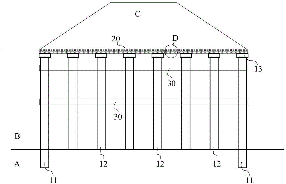
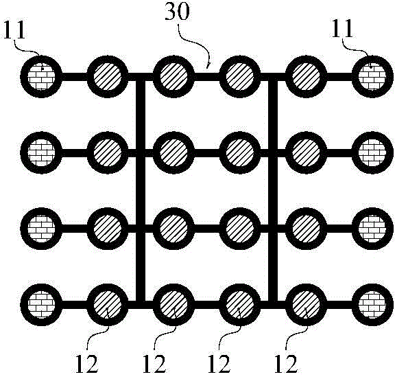
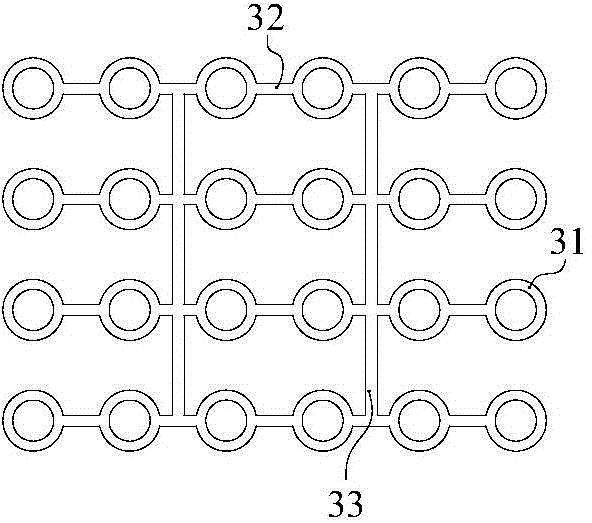
[0014] refer to figure 1 and figure 2 , the soft soil foundation composite pile network structure includes: bored cast-in-situ piles 12, which are arranged at intervals around the boundary of the filling body C, and the bottom of the piles enters a certain depth in the underlying bedrock layer A of the soft soil layer B. When the width of the filling body C is large , the bored piles 12 can be arranged in multiple rows; the press-in piles 12 are arranged at intervals in the soft soil layer B within the scope of the bored piles 11, and the bottom is pressed into the top surface of the bedrock layer A; the pile cap 13 is arranged on Bored cast-in-place piles 11 and tops of pressed-in piles 12 are integrated with them; guiding and fixed frame lattice 30 is located in soft soil layer B, forming lateral constraints on each bored piles 12 and pressed-in pil...


PUM


Abstract

The invention discloses a soft soil foundation combined pile net structure, aims at effectively improving reinforcing effect and saving project investment and comprises cast-in-place piles, pressed piles, pile caps, guide fixing frame lattices and a cushion body. The cast-in-place piles are arranged around the boundary of a filling body at intervals, bottoms of the cast-in-place piles enter a bedrock layer below a soft soil layer by certain depth, the pressed piles are arranged in the soft soil layer within a range of the cast-in-place piles at intervals, bottoms of the pressed piles are pressed in the top surface of the bedrock layer, the pile caps are arranged at the tops of the cast-in-placed piles and the pressed piles and fixedly connected with the cast-in-placed piles and the pressed piles, the guide fixing frame lattices are positioned in the soft soil layer and transversely restrain the cast-in-place piles and the pressed piles, and the cushion body is laid between the tops of the piles caps and the undersurface of the filling body.

Description

technical field [0001] The invention relates to civil engineering, in particular to foundation reinforcement engineering of soft soil on bedrock body. Background technique [0002] In engineering construction, there are a large number of foundation projects with soft soil overlying the bedrock. To build a filling project on the soft soil foundation above the bedrock, it is necessary to carry out composite foundation reinforcement treatment for the foundation. Usually, the soft soil Cement-soil mixing piles and high-pressure jet grouting piles can be used for reinforcement. However, when the soft soil is thick or the filling height of the upper filling project is relatively large, the bearing capacity of the foundation after cement-soil mixing piles or high-pressure jet grouting piles is reduced. Settlement control often cannot meet engineering requirements. In addition, when the soft soil contains a large amount of organic matter, the pile quality of cement-soil mixing piles...

Claims


Application Information

Patent Timeline
Patent Type & Authority Applications(China)
IPC IPC(8): E02D27/12
Inventor 姚裕春袁碧玉李安洪邓敏庞应刚魏永幸龚建辉葛学军曾永红李井元赵青海吴沛沛李宁郭在旭
Owner CHINA RAILWAY ERYUAN ENG GRP CO LTD
Why Eureka
Try Eureka