Single reheat pressurizing steam turbine thermodynamic system

A thermal system and thermal pressurization technology, which is applied in the direction of steam engine installation, steam application, mechanical equipment, etc., can solve the problems of low return on investment, high investment in the overall renovation project, and has not been applied and promoted.

Active Publication Date: 2014-05-28
CHINA POWER ENG CONSULTING GRP CORP EAST CHINA ELECTRIC POWER DESIGN INST
View PDF6 Cites 4 Cited by
  • Summary
  • Abstract
  • Description
  • Claims
  • Application Information

AI Technical Summary

Problems solved by technology

[0008] However, due to the transformation of subcritical low-parameter units into ultra-supercritical high-parameter units, it is necessary to replace new boilers, increase front cylinders, replace heaters, feed water pumps and other main and auxiliary equipment, and the investment in the overall transformation project is very

Method used


Image

  • Single reheat pressurizing steam turbine thermodynamic system
  • Single reheat pressurizing steam turbine thermodynamic system
  • Single reheat pressurizing steam turbine thermodynamic system

Examples


Embodiment 1

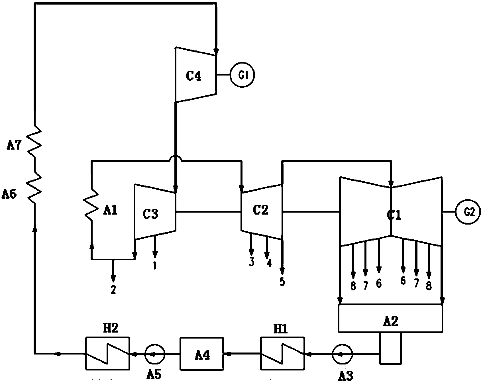
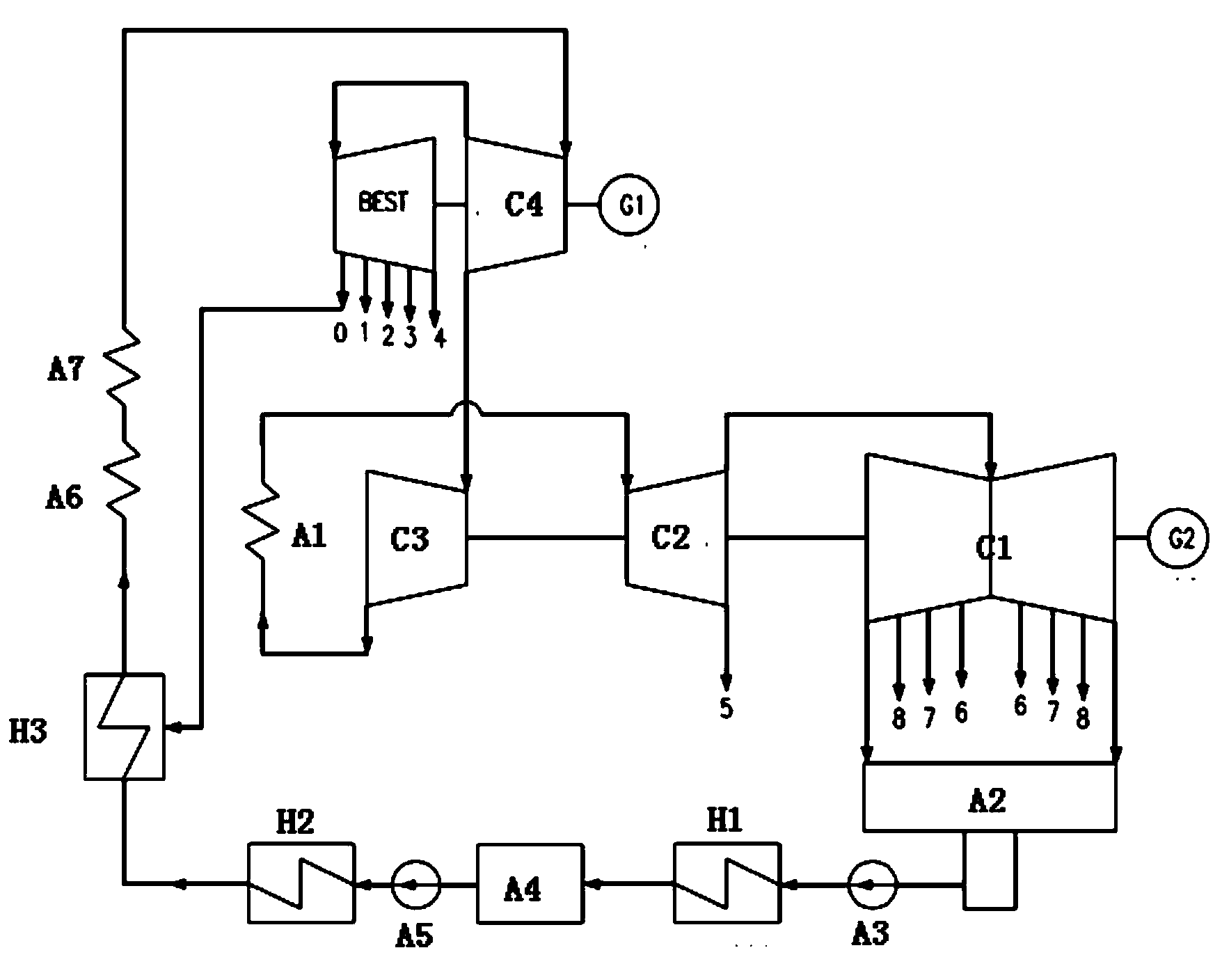
[0039] figure 2 It is a structural diagram showing the thermal system of the once-reheated supercharged turbine in Embodiment 1 of the present invention. and figure 1 In comparison, it can be seen that in figure 2 In the once-reheated supercharged steam turbine thermal system shown, the back pressure extraction cylinder BEST and the second high pressure heater H3 that are not in the prior art are added. As shown in the figure, the thermal system of the once-reheated supercharged steam turbine has a reheater A1, a condenser A2, a condensate pump A3, a deaerator A4, a feed water pump group A5, an economizer A6, a superheater A7, a back Pressure extraction steam cylinder BEST, low pressure cylinder C1, medium pressure cylinder C2, high pressure cylinder C3, super high pressure cylinder C4 first generator G1, second generator G2, low pressure heater H1, first high pressure heater H2, and second High pressure heater H3. Among them, the ultra-high pressure cylinder C4 and the ...

Embodiment 2

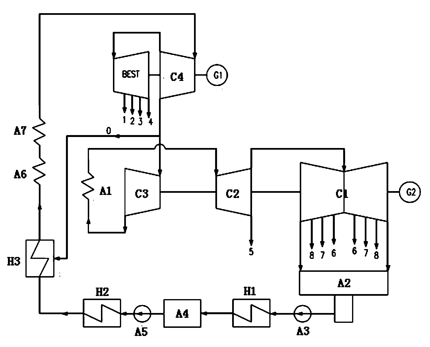
[0046] image 3 It is a structural diagram showing the thermal system of the once-reheated supercharged turbine in Embodiment 2 of the present invention.

[0047] Embodiment 2 of the present invention is similar to Embodiment 1, except that the exhaust pressure of the ultra-high pressure cylinder is reduced, and the steam extraction of the newly added second high-pressure heater H3 is changed from the exhaust steam of the ultra-high pressure cylinder C4. As a result, no adjustment stage is required for the high-pressure cylinder C3, which reduces throttling losses and improves the internal efficiency of the high-pressure cylinder C3.

Embodiment 3

[0049] Figure 4 It is a structural diagram showing the thermal system of the once-reheated supercharged turbine in Embodiment 3 of the present invention.

[0050] Embodiment 3 of the present invention is similar to Embodiment 2, except that a feed water booster pump A8 is added at the entrance of the newly added second high-pressure heater H3. Therefore, when transforming the old low-parameter unit, it is not necessary to replace the feed water pump unit and its drive unit or motor, nor to replace the original multi-stage high-pressure heater, which can significantly reduce the project cost.


PUM


Abstract

The invention discloses a single reheat pressurizing steam turbine thermodynamic system. The single reheat pressurizing steam turbine thermodynamic system is characterized in that a high parameter steam turbine generator set is provided with a back pressure steam extraction cylinder, the back pressure steam extraction cylinder and an ultra-high pressure cylinder are arranged to be separated or combined, a heat return and single reheat thermodynamic circulation system is provided with a second high pressure heater used for heat return, and extracted steam of the second high pressure heater is guided and connected from exhausted steam of the back pressure steam extraction cylinder. According to the single reheat pressurizing steam turbine thermodynamic system, the electricity generation heat efficiency is further improved, coal consumption for power supply is reduced, and the capacity of the set is obviously improved.

Description

technical field [0001] The invention relates to a once-reheated supercharged steam turbine thermal system, in particular to a once-reheated supercharged steam turbine thermal system with a back pressure extraction cylinder. Background technique [0002] According to the steam inlet parameters from low to high, thermal power generating units can be divided into subcritical, supercritical and ultra supercritical. The higher the inlet steam parameter, the higher the thermal efficiency of power generation. [0003] For the thermal power generation units built in the 1980s and 1990s and which have been in operation for a long time, due to the technical limitations of their construction years, subcritical (typical parameters 16.7MPa, 538°C) low-parameter turbogenerators are mostly used, and the coal consumption for power supply is about 320g / kW.h. The new thermal power generation units built in recent years mostly adopt supercritical (typical parameters 24.2MPa, 566°C) and ultra...

Claims


Application Information

Patent Timeline
IPC IPC(8): F01K23/02F01K17/00
Inventor 申松林刘鹤忠陈仁杰叶勇健施刚夜兰花姚君
Owner CHINA POWER ENG CONSULTING GRP CORP EAST CHINA ELECTRIC POWER DESIGN INST
Why Eureka
Try Eureka