The method of judging the long burning of the torch light
A technology of long-bright lights and torches, which is applied in the direction of using electric radiation detectors for photometry, etc., can solve problems such as effective use and unstable output signals, achieve good technical effects, improve reliability, and output signals are stable and reliable.
- Summary
- Abstract
- Description
- Claims
- Application Information
AI Technical Summary
Problems solved by technology
Method used
Image
Examples
Embodiment 1
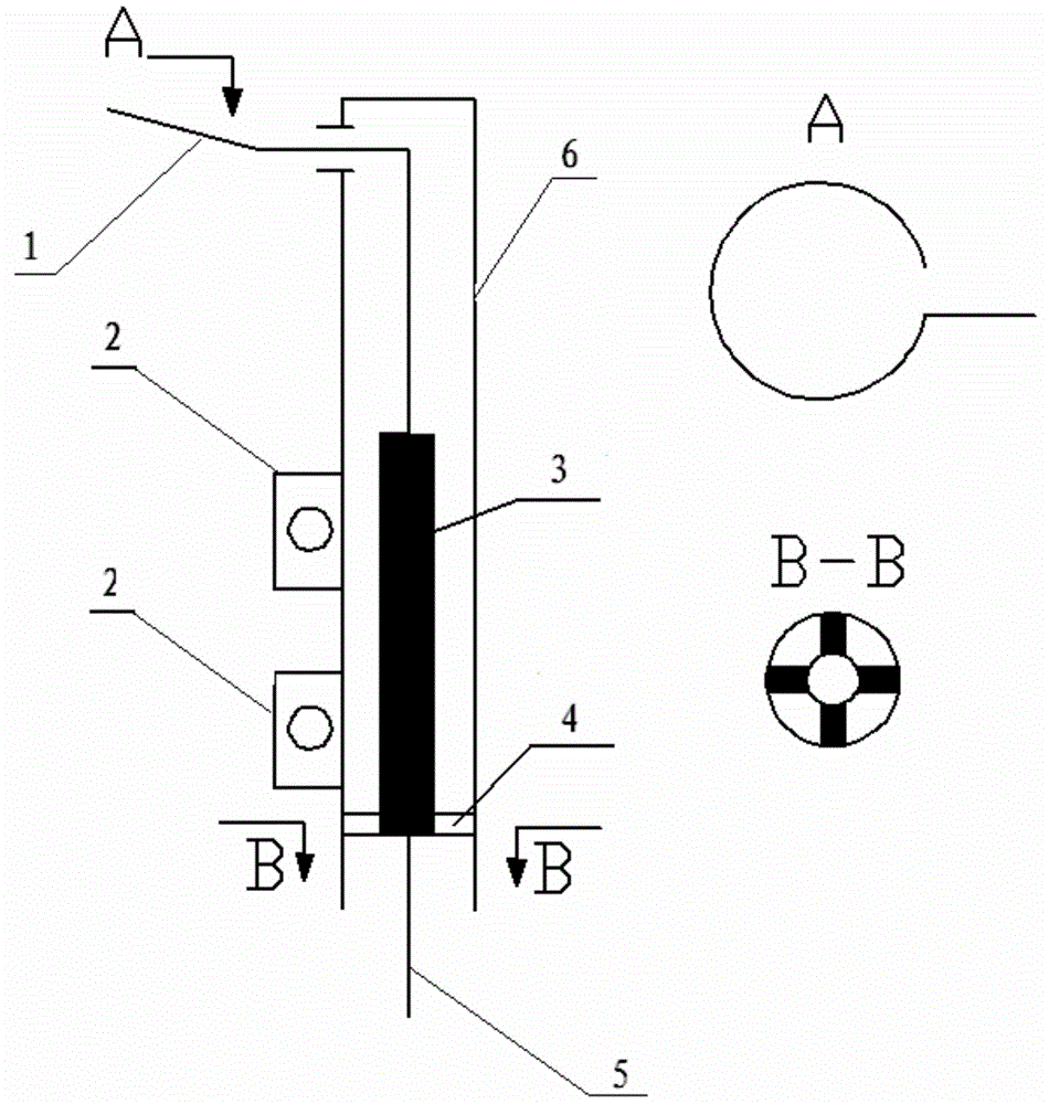
[0018] figure 1 It is a structural schematic diagram of the detector of the present invention, the detector includes a probe 1, a high temperature resistant insulating ceramic 3, a housing 6, a mounting rib 2, a connecting rib 4, a high temperature resistant cable 5, the housing 6 is a cylinder, and the probe One end of the needle 1 is located outside the shell 6, and the other end is connected to the high temperature resistant cable 5, the high temperature resistant cable 5 is located outside the shell 6, and the probe 1 inside the shell 6 is surrounded by high temperature insulating ceramic 3, fixed by the connecting rib 4 Inside the casing 6, the insulation between the casing and the probe is guaranteed under severe working conditions such as high temperature. The outside of the casing 6 is provided with a mounting rib 2 to connect with the light. 15 degrees, the length of the probe 1 inside the warm insulating ceramic 3 accounts for 50% of the total length of the probe 1 ....
Embodiment 2
[0023] figure 1 It is a structural schematic diagram of the detector of the present invention, the detector includes a probe 1, a high temperature resistant insulating ceramic 3, a housing 6, a mounting rib 2, a connecting rib 4, a high temperature resistant cable 5, the housing 6 is a cylinder, and the probe One end of the needle 1 is located outside the shell 6, and the other end is connected to the high temperature resistant cable 5, the high temperature resistant cable 5 is located outside the shell 6, and the probe 1 inside the shell 6 is surrounded by high temperature insulating ceramic 3, fixed by the connecting rib 4 Inside the casing 6, the insulation between the casing and the probe is guaranteed under severe working conditions such as high temperature. The outside of the casing 6 is provided with a mounting rib 2 to connect with the light. 10 degrees, the length of the probe 1 inside the warm insulating ceramic 3 accounts for 35% of the total length of the probe 1 ....
Embodiment 3
[0028] figure 1 It is a structural schematic diagram of the detector of the present invention, the detector includes a probe 1, a high temperature resistant insulating ceramic 3, a housing 6, a mounting rib 2, a connecting rib 4, a high temperature resistant cable 5, the housing 6 is a cylinder, and the probe One end of the needle 1 is located outside the shell 6, and the other end is connected to the high temperature resistant cable 5, the high temperature resistant cable 5 is located outside the shell 6, and the probe 1 inside the shell 6 is surrounded by high temperature insulating ceramic 3, fixed by the connecting rib 4 Inside the casing 6, the insulation between the casing and the probe is guaranteed under severe working conditions such as high temperature. The outside of the casing 6 is provided with a mounting rib 2 to connect with the lamp. The part of the probe 1 located outside the casing 6 is provided with a certain upward angle, the angle is 30 degrees, the length...
PUM
 Abstract
Description
Claims
Application Information
 - R&D
- Intellectual Property
- Life Sciences
- Materials
- Tech Scout
- Unparalleled Data Quality
- Higher Quality Content
- 60% Fewer Hallucinations
Browse by: Latest US Patents, China's latest patents, Technical Efficacy Thesaurus, Application Domain, Technology Topic, Popular Technical Reports.
© 2025 PatSnap. All rights reserved.Legal|Privacy policy|Modern Slavery Act Transparency Statement|Sitemap|About US| Contact US: help@patsnap.com

