
Automatic dual-exciting-coil conductor defect flaw detection device and method

A technology for coil conductors and flaw detection devices, which is applied to measurement devices, instruments, and material analysis by electromagnetic means, can solve problems such as low sensitivity, damage, and radiation pollution in the environment, and achieve high detection accuracy, high efficiency, and improved detection. effect of ability

Active Publication Date: 2014-05-28
JIANGSU UNIV OF TECH
View PDF8 Cites 5 Cited by
  • Summary
  • Abstract
  • Description
  • Claims
  • Application Information

AI Technical Summary

Problems solved by technology

Ultrasonic flaw detection is a manual operation. The display of defects by ultrasonic flaw detection is not intuitive. It needs a couplant. The flaw detection technology is difficult and easily affected by subjective and objective factors. It requires experienced inspectors to distinguish the type of defect. It is suitable for thicker parts. Inspection; radiographic flaw detection has side effects or even certain damage to the human body, has adverse effects on other sensitive objects, and has radiation pollution to the environment; and the current ordinary eddy current flaw detection, due to the use of single-coil technology, has no comparison between defects and non-defects, and the sensitivity lower

Method used


Image

  • Automatic dual-exciting-coil conductor defect flaw detection device and method
  • Automatic dual-exciting-coil conductor defect flaw detection device and method
  • Automatic dual-exciting-coil conductor defect flaw detection device and method

Examples


Embodiment Construction

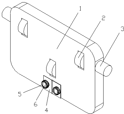
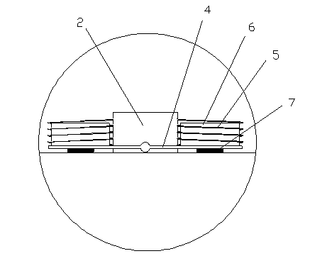
[0019] The present invention is described in further detail now in conjunction with accompanying drawing. These drawings are all simplified schematic diagrams, which only illustrate the basic structure of the present invention in a schematic manner, so they only show the configurations related to the present invention.

[0020] Such as Figure 1-3 As shown, an automatic flaw detection device for conductor defects with double excitation coils includes a power trolley 1, a single-chip microcomputer, a detection board 4, an excitation coil 5, a giant magnetoresistive sensor 6 and a relay. The single-chip microcomputer is arranged inside the power trolley 1, and the detection The board 4 is arranged on one end of the bottom surface of the power trolley 1, and the two ends of the detection board 4 are elastically connected to the bottom surface of the power trolley 1 through springs 7 respectively. The relay is connected with the detection board 4 and can control both sides of the ...


PUM


Abstract

The invention relates to an automatic dual-exciting-coil conductor defect flaw detection device and a method. The device comprises a power trolley, a singlechip, a detection plate, exciting coils, giant magnetoresistance sensors and a relay, wherein the singlechip is arranged in the power trolley; the detection plate is arranged at one end of the bottom surface of the power trolley; two ends of the detection plate are respectively connected with the bottom surface of the power trolley elastically by springs; the relay is connected with the detection plate, and can control two sides of the detection plate to overturn downwards; the two exciting coils are fixed on the detection plate, and are symmetrically arranged on the detection plate, and are internally provided with the giant magnetoresistance sensors respectively; the bottom surfaces of the giant magnetoresistance sensors and the bottom ends of the exciting coils are at the same horizontal level; the giant magnetoresistance sensors are electrically connected with the singlechip. The dual-exciting-coil conductor automatic defect flaw detection device and the method effectively improve the capability of detecting the deep-layer defect and surface micro defect of the system, are high in detection accuracy and efficiency, and have popularization and using values.

Description

technical field [0001] The invention relates to the technical field of nondestructive testing, in particular to an automatic flaw detection device and a flaw detection method for conductor defects with double excitation coils. Background technique [0002] The role of non-destructive testing technology in the quality assurance system has increasingly shown its importance and necessity, and has become an important means to control product quality and ensure the safe operation of in-service equipment. Ultrasonic, X-ray, eddy current and other methods are commonly used in non-destructive testing. Ultrasonic flaw detection is a manual operation. The display of defects by ultrasonic flaw detection is not intuitive. It needs a couplant. The flaw detection technology is difficult and easily affected by subjective and objective factors. It requires experienced inspectors to distinguish the type of defect. It is suitable for thicker parts. Inspection; radiographic flaw detection has...

Claims


Application Information

Patent Timeline
IPC IPC(8): G01N27/90G01N27/904
Inventor 杨龙兴杨浩轩周德强
Owner JIANGSU UNIV OF TECH
Learn More