Electromagnet test piece work air gap adjusting device applied to micro electromagnetic valve

A technology of working air gap and adjusting device, which is applied in the field of electromagnets, can solve the problems of wearing pads, long test cycle, and prolonging the test cycle, so as to achieve the effects of convenient disassembly and installation, shortening the test cycle, and saving raw materials

Inactive Publication Date: 2014-05-28
ZHEJIANG UNIV
View PDF6 Cites 9 Cited by
  • Summary
  • Abstract
  • Description
  • Claims
  • Application Information

AI Technical Summary

Problems solved by technology

The first test method, in order to obtain the relationship between multiple groups of different working air gaps and the performance of the micro-electromagnet, needs to make multiple test pieces, the test period is long, the consumption of raw materials is large, and the cost is high
The second test method needs to process multiple groups of pads with different thicknesses. Compared with the previous method, although it can reduce the amount of raw materials used, in the test process, in order to adjust the working air gap, different thicknesses need to be disassembled each time. block
In this way, multiple disassembly and assembly of the test piece will not only wear out the pads, resulting in inaccurate working gaps of the miniature electromagnets, but also prolong the test cycle

Method used


Image

  • Electromagnet test piece work air gap adjusting device applied to micro electromagnetic valve
  • Electromagnet test piece work air gap adjusting device applied to micro electromagnetic valve
  • Electromagnet test piece work air gap adjusting device applied to micro electromagnetic valve

Examples


Embodiment Construction

[0025] The present invention will be further described below in conjunction with the accompanying drawings.

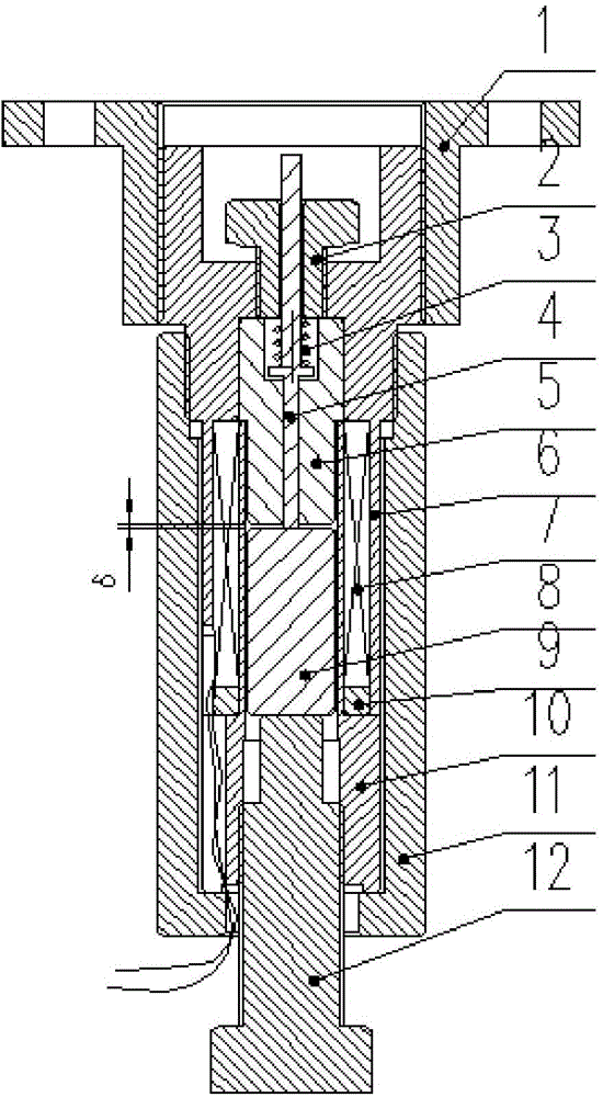
[0026] refer to figure 1 A device for adjusting a working air gap of an electromagnet test piece for a miniature solenoid valve, comprising an electromagnet test piece, a working air gap adjusting mechanism, and a test bench installation and fixing mechanism. The electromagnet test piece includes a thrust rod 4, a preload spring 3, a static iron core 5, an armature 8, a base 10, a coil spacer 9, a coil 7 and an electromagnet jacket 6; the working air gap adjustment structure includes a spring adjustment Bolt 2 and armature adjustment bolt 12; the test bench installation and fixing structure includes coupling sleeve 11 and fixed sleeve 1.

[0027] During the installation process, firstly, the coil spacer 9 is fitted on the base 10 through clearance fit, the coil 7 is wound on the base 10, and two enameled wires are drawn out, and the enameled wire winding thickness is ...


PUM


Abstract

The invention provides an electromagnet test piece work air gap adjusting device applied to a micro electromagnetic valve. The device comprises an electromagnet test piece, a work air gap adjusting mechanism and a test bench installation and fixation mechanism. The upper end face of a static iron core abuts against the lower end face of a middle hole of an electromagnet coat. A thrust rod is arranged in a middle small hole of the static iron core through clearance fit. The upper end face of an armature abuts against the lower end face of the thrust rod. A coil cushion block is arranged on a base through clearance fit. The thrust rod is arranged in a small hole of a spring adjustment bolt through clearance fit. The lower end face of the spring adjustment bolt abuts against a pre pressing spring. An armature adjusting bolt is arranged in an inner screw thread hole of the base through screw thread connection. The upper end face of the armature adjusting bolt abuts against the lower end face of the armature. A connecting sleeve is arranged on the electromagnet coat through screw thread connection. A fixation sleeve is arranged on the electromagnet coat through screw thread connection. A light hole on the electromagnet coat is used for the installation on a micro electromagnet test bench.

Description

technical field [0001] The invention relates to an electromagnet, in particular to an electromagnet test piece for a miniature electromagnetic valve. Background technique [0002] The electromagnet is an important component in the solenoid valve, and its performance directly affects the quality of the solenoid valve. With the attention of green technology to energy saving and environmental protection and the installation requirements of hydraulic components in some special industrial occasions, solenoid valves are developing in the direction of low power consumption and miniaturization. In the development process of the micro solenoid valve, the micro electromagnet and the hydraulic valve are usually developed separately. Among the factors affecting the performance of the electromagnet, the working air gap that it relies on to generate mechanical displacement and work is an important parameter. The calculation, inspection, and adjustment of the working air gap have an impo...

Claims


Application Information

Patent Timeline
Patent Type & Authority Applications(China)
IPC IPC(8): G01R33/12H01F7/121
Inventor 徐兵杨梅生张军辉沙林峰沈云栋
Owner ZHEJIANG UNIV
Why Eureka
Try Eureka