Framework type spatial foldable antenna unfolding mechanism

A deployment mechanism and space technology, applied in the directions of foldable/retractable loop antennas, antenna supports/installation devices, etc., can solve the problems of poor synchronization of deployment and retraction, large number of rods, complex structure, etc. Small number of pieces, not easy to get stuck

Inactive Publication Date: 2014-05-28
HARBIN INST OF TECH SHENZHEN GRADUATE SCHOOL
View PDF4 Cites 9 Cited by
  • Summary
  • Abstract
  • Description
  • Claims
  • Application Information

AI Technical Summary

Problems solved by technology

The disadvantages of this solution are: 1. There are many rods, the structure is more complicated, and the reliability is low; 2. Two sliders are used to drive, the synchronization of unfolding and retracting is poor, and it is easy to get stuck during the unfolding and retracting process

Method used


Image

  • Framework type spatial foldable antenna unfolding mechanism

Examples


Embodiment 1

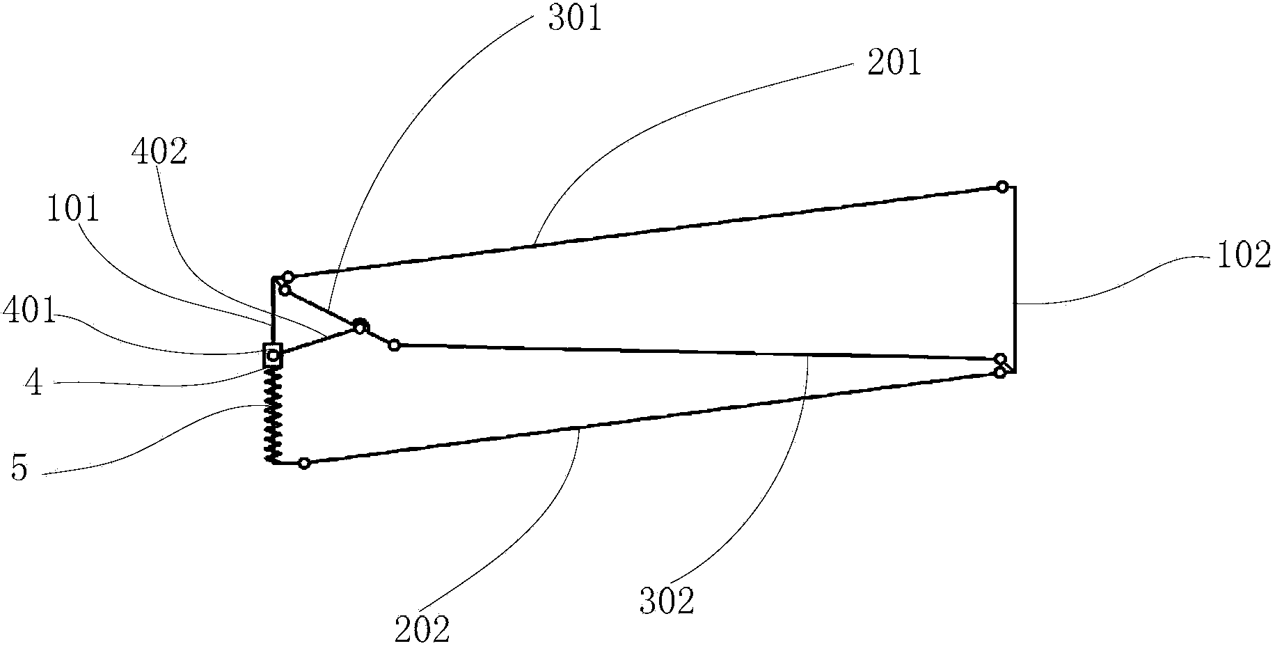
[0023] The structure-type space deployable antenna deployment mechanism of this embodiment includes several identical basic deployment units; figure 1 As shown, the basic expansion unit includes:

[0024] The first vertical rod 101 and the second vertical rod 102, when the basic expansion unit is deployed, the first vertical rod 101 and the second vertical rod 102 are vertically arranged in parallel;

[0025] The upper chord 201, the beginning of the upper chord 201 is connected to the upper end of the first vertical rod 101 through a rotating pair; the end of the upper chord 201 is connected to the upper end of the second vertical rod 102 through a rotating pair;

[0026] The lower chord 202, the beginning of the lower chord 202 is connected to the lower end of the first vertical rod 101 through a rotating pair; the end of the lower chord 202 is connected to the lower end of the second vertical rod 102 through a rotating pair;

[0027] Up slant bar 301 and down slant bar 302...

Embodiment 2

[0032] The difference between this embodiment and Embodiment 1 is that the lengths of the first vertical rod, the second vertical rod, the upper chord and the lower chord of the basic expansion unit are the same.


PUM


Abstract

The invention provides a framework type spatial foldable antenna unfolding mechanism. The framework type spatial foldable antenna unfolding mechanism comprises a plurality of same basic unfolding units. Each basic unfolding unit comprises a first stand rod, a second stand rod, an upper chord rod, a lower chord rod, an upper inclined rod and a lower inclined rod, wherein the starting end of the upper chord rod is connected to the upper end of the first stand rod through a rotating pair, the tail end of the upper chord rod is connected to the upper end of the second stand rod through a rotating pair, the starting end of the lower chord rod is connected to the lower end of the first stand rod through a rotating pair, the tail end of the lower chord rod is connected to the lower end of the second stand rod through a rotating pair, the starting end of the upper inclined rod is connected to the upper end of the first stand rod through a rotating pair, the starting end of the lower inclined rod is connected to the lower end of the second stand rod through a rotating pair, the tail end of the upper inclined rod and the tail end of the lower inclined rod are connected with each other through a rotating pair, the upper inclined rod is movably connected with the first stand rod through a sliding block crankshaft mechanism, the first stand rod is sleeved with a sliding block, one end of a crankshaft is connected to the upper inclined rod through a rotating pair, the other end of the crankshaft is connected to the sliding block through a rotating pair, the first stand rod is sleeved with a driving spring, one end of the driving spring is fixed to the lower end of the first stand rod, and the other end of the driving spring is connected to the sliding block.

Description

technical field [0001] The invention belongs to the technical field of aerospace equipment and equipment, and relates to a frame-type space expandable antenna deployment mechanism, which can be used for large-diameter parabolic antennas of artificial satellites and space probes. Background technique [0002] In recent years, with the continuous increase of human space activities, space deployable antennas have played a very important role in such as long-distance communication, earth monitoring and various outer space explorations. According to the difference of the reflecting surface medium, the spatial deployable antennas can be divided into three types, which are solid surface deployable antennas, inflatable deployable antennas and metal mesh deployable antennas. Among them, the metal mesh deployable antenna is the most widely used because of its high storage ratio and light weight. There are many types of metal mesh deployable antennas. The Japan Aerospace Exploration A...

Claims


Application Information

Patent Timeline
Patent Type & Authority Applications(China)
IPC IPC(8): H01Q7/02H01Q1/12
Inventor 李兵楚争荣黄海林邓宗全
Owner HARBIN INST OF TECH SHENZHEN GRADUATE SCHOOL
Why Eureka
Try Eureka