Random spread spectrum modulation

A spread spectrum, pseudo-random technology, applied in the field of random spread spectrum modulation, which can solve the problems of high power and area consumption

Active Publication Date: 2014-05-28
INFINEON TECH AG
View PDF8 Cites 6 Cited by
  • Summary
  • Abstract
  • Description
  • Claims
  • Application Information

AI Technical Summary

Problems solved by technology

The digital core must be constrained to this frequency, resulting in higher power and area consumption
Therefore, low-frequency up-scaling modulation can introduce phase accumulation in time, which can cause problems in the operation of synchronous data interfaces between digital cores and other unmodulated cores

Method used


Image

  • Random spread spectrum modulation
  • Random spread spectrum modulation
  • Random spread spectrum modulation

Examples


Embodiment Construction

[0015] overview

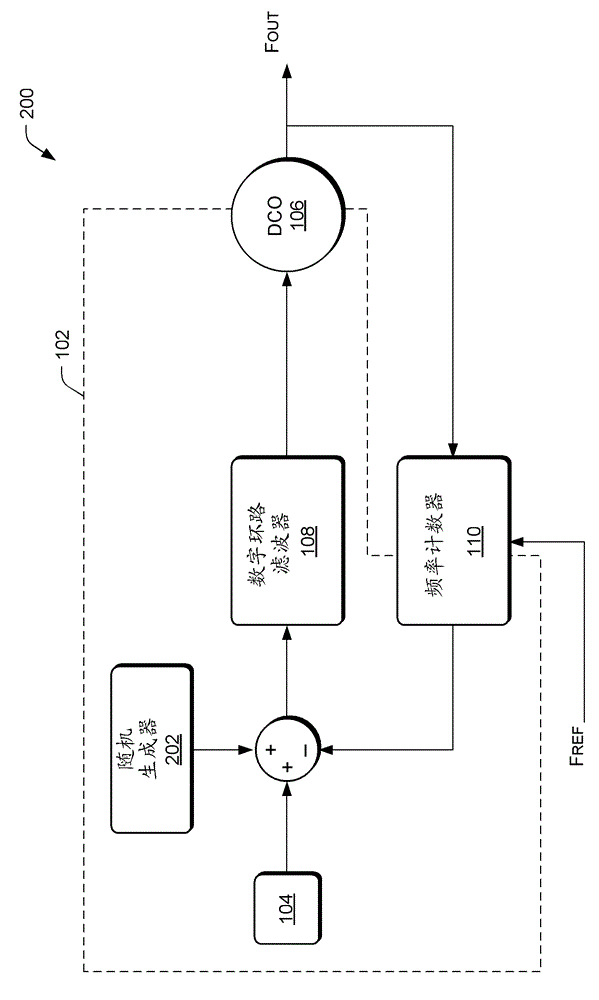
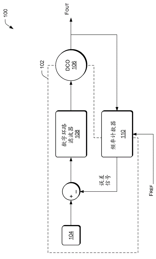
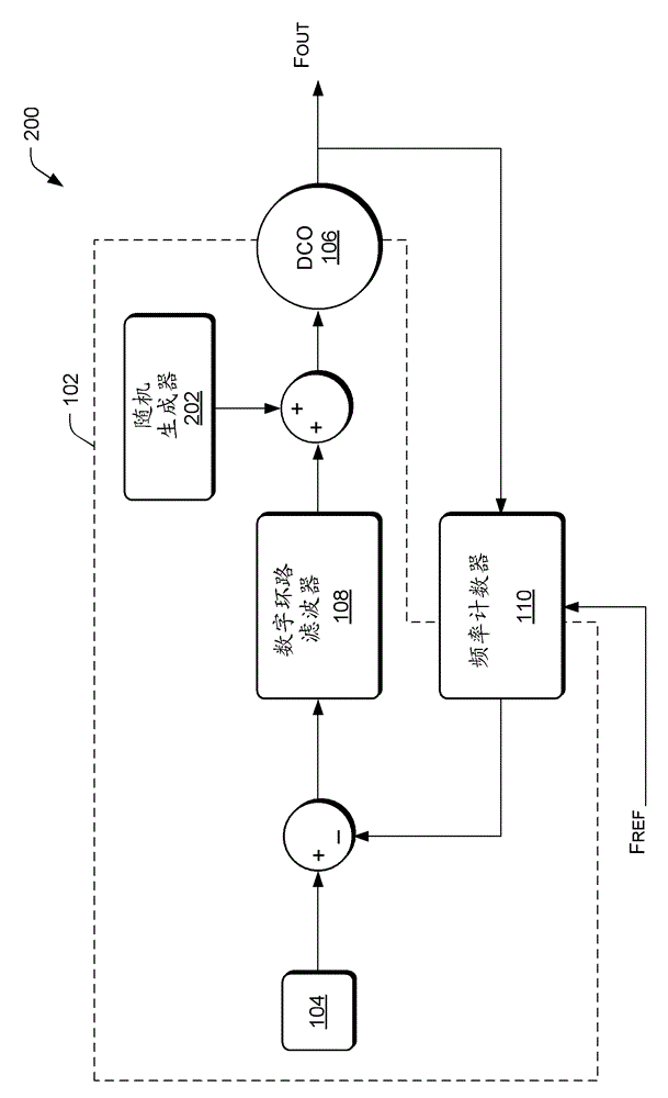
[0016] Embodiments of representative devices and techniques provide a spread spectrum clock signal. In a frequency synthesizer such as a Phase Locked Loop (PLL) device, a clock signal is generated based on an input signal. A sequence of values ​​can be generated and used to modulate the output signal of a frequency synthesizer to produce a spread spectrum clock signal. In various implementations, the sequence of values ​​may be a random or pseudo-random sequence of values. In an alternative embodiment, one or more sequences of values ​​may be added to the signal path of the frequency synthesizer at one or more points along the signal path.

[0017] In various embodiments, the sequence of values ​​modulates the output signal of the frequency synthesizer, for example, with a high modulation frequency in the MHz range. In other embodiments, the modulation profile, and thus the spread spectrum clock signal, is centered around the nominal frequency of the clo...


PUM


Abstract

The present invention relates to a random spread spectrum modulation. Representative implementations of devices and techniques provide a spread spectrum clocking signal. In a frequency synthesizer, a sequence of values may be generated and used to modulate a frequency of an input signal to the frequency synthesizer.

Description

technical field [0001] The present invention relates to random spread spectrum modulation. Background technique [0002] Typically, the clock signals used in the digital core are delivered by an on-chip clock generation unit or a frequency synthesizer. The clock generation unit may be a phase-locked loop (PLL) device, which may also be implemented in the form of a digital PLL. However, such clock signals can be a source of electromagnetic interference (EMI) to other parts of the system utilizing the digital core. Unwanted electromagnetic energy can propagate throughout the system, or into the external environment, and adversely affect other susceptible devices. [0003] For example, Electromagnetic Compatibility (EMC) requirements in various industries such as the automotive and consumer appliance industries place strict limits on the emission of electromagnetic radiation from electronic devices. Accordingly, spread spectrum clocks have been developed for digital cores us...

Claims


Application Information

Patent Timeline
Patent Type & Authority Applications(China)
IPC IPC(8): H03L7/18
CPCH04B1/707H04B15/04
Inventor N.达达尔特W.格罗利奇P.普里德尼希
Owner INFINEON TECH AG
Why Eureka
Try Eureka