Supercharge Your Innovation With Domain-Expert AI Agents!

Shaft with a flange connection

A flange and forging technology, which is applied in the field of flange connection devices, can solve the problems of increasing time consumption and achieve the effect of increasing static friction and simple and quick replacement

Inactive Publication Date: 2014-05-28
KHD HUMBOLDT WEDAG GMBH
View PDF5 Cites 5 Cited by
  • Summary
  • Abstract
  • Description
  • Claims
  • Application Information

AI Technical Summary

Problems solved by technology

However, the disadvantage of the shrink disk is that in order to replace the rollers, the shrink disk must be removed each time and reinstalled after the replacement, which significantly increases the time consumption during the replacement, especially in the case of mechanical shrink disks.

Method used


Image

  • Shaft with a flange connection

Examples


Embodiment Construction

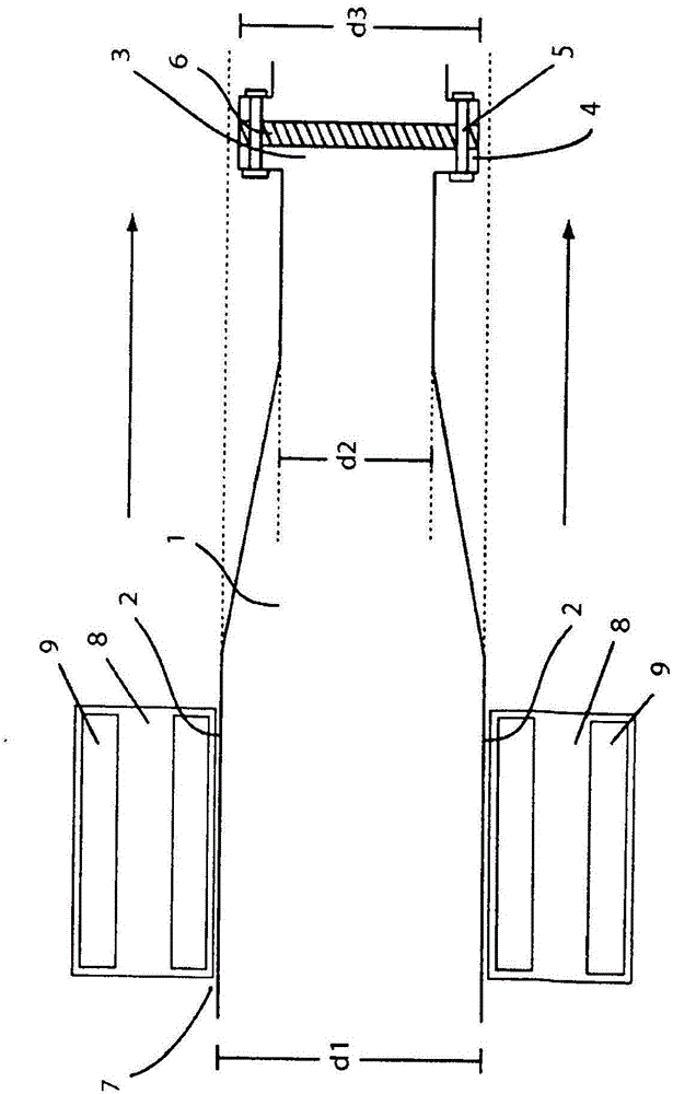
[0017] exist figure 1 shows a shaft 1 which has a diameter d1 at the location of the rolling bearing housing 2 . The shaft 1 tapers conically in the direction of the flange 3 and has a diameter d2 in this narrower region. At the narrower end of the shaft 1 there is a flange 3 with a diameter d3 comprising a flange plate 4 which in this example is forged onto the shaft 1 and is thus integral with said shaft. The flange is connected to the flange piece 4 by screws 5 . In order to transmit the torque, friction discs 6 for evenly distributing the force caused by rotation on the flange discs 4 are installed between the flanges. On the thicker end of the shaft 1 on the hub 7 is mounted a rolling bearing 8 with rolling bodies 9 therein. The diameter d3 of the flange connection 3 is slightly smaller than the inner diameter d1 on which the rolling bearing 8 rests. It is thus possible to remove the rolling bearing 8 on the hub 7 from the shaft in the direction of the arrow after dis...


PUM


Abstract

The invention relates to a flange connection on a shaft (1) having at least two diameters (d1, d2) of different size, wherein the diameter (d3) of the flange connection is smaller than the diameter (d1) of the rolling bearing seat (2). Machine parts on the shaft can thereby be rapidly and simply interchanged without the flange (3) having to be removed in the process.

Description

technical field [0001] The invention relates to a flange connection on a shaft, which enables quick and simple exchange of machine parts on the shaft, without having to remove the flange. Background technique [0002] Usually a shoulder on a constructional element such as a tube, shaft or housing is called a flange and is used to connect or couple the corresponding constructional element with another element. Flange pieces are typically provided on the flange, the flange pieces surround the component at the connection point of the component, and the flanges are connected to one another by means of the flange pieces by compression. The connection can be made irreversible, for example by welding the flanges, but can also be made reversible, for example by screwing the flanges onto holes provided for this purpose. [0003] In machine construction, flanges are often used to be implemented on shafts, for example in planetary gears between transmission and shaft. A shaft in its ...

Claims


Application Information

Patent Timeline
Patent Type & Authority Applications(China)
IPC IPC(8): F16C3/02F16C13/00F16D1/033B30B3/00B02C4/28
CPCB30B3/00F16C3/02F16D1/02F16C13/00B02C4/28F16D1/027F16D1/033F16B2200/50
Inventor M·弗兰根贝格
Owner KHD HUMBOLDT WEDAG GMBH
Features
  • R&D
  • Intellectual Property
  • Life Sciences
  • Materials
  • Tech Scout
  • Unparalleled Data Quality
  • Higher Quality Content
  • 60% Fewer Hallucinations
Learn More