Light intensity distribution conversion element, surface light source device and liquid crystal display device

一种光强度分布、转换元件的技术,应用在光学元件、光导、光学等方向,能够解决很难得到高均匀性面状光等问题,达到颜色再现范围宽、均匀性优异、简洁结构的效果

Active Publication Date: 2017-02-15
MITSUBISHI ELECTRIC CORP
View PDF11 Cites 0 Cited by
  • Summary
  • Abstract
  • Description
  • Claims
  • Application Information

AI Technical Summary

Problems solved by technology

[0005] However, on the other hand, when a laser that is a point light source and emits light with high directivity is used as the light source of the surface light source device, it is difficult to obtain planar light with a highly uniform spatial light intensity distribution.

Method used


Image

  • Light intensity distribution conversion element, surface light source device and liquid crystal display device
  • Light intensity distribution conversion element, surface light source device and liquid crystal display device
  • Light intensity distribution conversion element, surface light source device and liquid crystal display device

Examples


Embodiment approach 1

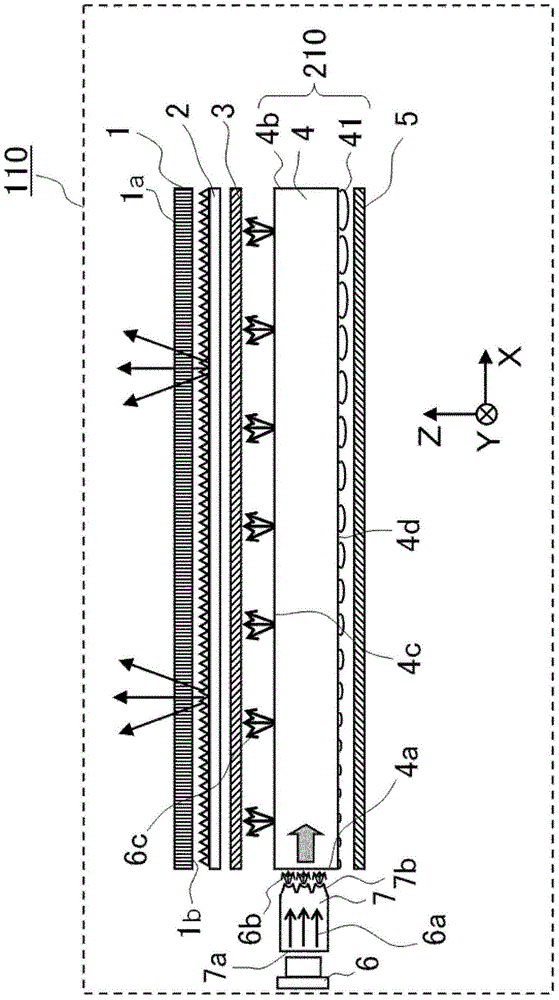
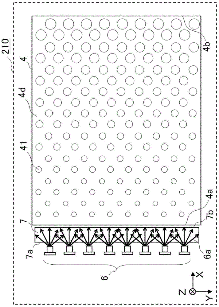
[0039] figure 1 It is a diagram schematically showing the configuration of a liquid crystal display device 110 as a transmissive display device according to Embodiment 1 of the present invention. for easy figure 1 For the description, let the short-side direction of the liquid crystal optical element 1 be the Y-axis direction, let the long-side direction be the X-axis direction, let the direction perpendicular to the X-Y plane be the Z-axis direction, and let the display surface 1a side of the liquid crystal display element 1 be + Z-axis direction. In addition, let the upper direction of the liquid crystal display device be the +Y axis direction, and let the light emission direction of the first light source 6 described later be the +X axis direction. In each of the following figures, when the liquid crystal display device is viewed from the front, the left side is defined as the +X-axis direction.

[0040] Such as figure 1 As shown, the liquid crystal display device 110 h...

Embodiment approach 2

[0092] Figure 12 It is a diagram schematically showing the configuration of a liquid crystal display device 120 as a transmissive display device according to Embodiment 2 of the present invention. The liquid crystal display device 120 of the second embodiment is the same as the liquid crystal display device 110 of the first embodiment except that the surface light source device 220 is different from the surface light source device 210 . That is, the liquid crystal optical element 1 , the optical sheets 2 and 3 , and the light reflection sheet 5 are the same as those of the liquid crystal display device 110 of the first embodiment. The same reference numerals are assigned to the same components as those of the liquid crystal display device 110 described in Embodiment 1, and detailed description thereof will be omitted.

[0093] The surface light source device 220 of Embodiment 2 includes a light source 8 , a light intensity distribution conversion element 9 , and a light guid...

Embodiment approach 3

[0107] Figure 16 It is a diagram schematically showing the configuration of a liquid crystal display device 130 as a transmissive display device according to Embodiment 3 of the present invention. also, Figure 17 It is a configuration diagram showing the surface light source device 230 from the −Z axis direction. In liquid crystal display device 130 of Embodiment 3, surface light source device 230 is different from surface light source device 220 of Embodiment 2 in that it has first light source 10 instead of light source 8 and also has second light source 11 . That is, the liquid crystal optical element 1 , the optical sheets 2 and 3 , the light guide plate 4 , the light reflection sheet 5 , and the light intensity distribution conversion element 9 are the same as those of the liquid crystal display device 120 of the second embodiment. In addition, the components of the liquid crystal display device 120 of the second embodiment that are the same as those of the liquid cry...


PUM


Abstract

The light intensity distribution conversion element (7) has a light incident surface (7a), a light exit surface (7b) and total reflection surfaces (70a, 70b). Directional light (6a) is incident on the light incident surface (7a). The light exit surface (7b) widens the angular intensity distribution of the light (6a), and has a concave curved surface (70c) with respect to the exit direction of the light (6a). The total reflection surfaces (70a, 70b) are close to or adjacent to the curved surface (70c), and are inclined relative to the emission direction of the light (6a), so that the light (6a) is totally reflected. The light (6a) reflected by the total reflection surface (70a, 70b) is emitted from the curved surface (70c).

Description

technical field [0001] The present invention relates to a light intensity distribution conversion element, a surface light source device, and a liquid crystal display device that have a laser as a light source and generate planar light with a uniform intensity distribution from point-like laser light. Background technique [0002] The liquid crystal display element itself included in the liquid crystal display device does not emit light. Therefore, the liquid crystal display device has a surface light source device as a light source for illuminating the liquid crystal display element on the back surface of the liquid crystal display element. Conventionally, cold-cathode fluorescent lamps have been mainly used as light sources of surface light source devices. The cold-cathode fluorescent lamp is a cold-cathode fluorescent lamp (hereinafter referred to as CCFL (Cold Cathode Fluorescent)) in which a phosphor is coated on the inner wall of a glass tube to obtain white light. H...

Claims


Application Information

Patent Timeline
Patent Type & Authority Patents(China)
IPC IPC(8): G02B6/00
CPCG02B6/0028G02B6/003G02B6/0068G02B6/0053G02B6/0061G02B6/0031G02B6/0025G02B27/0927
Inventor 西谷令奈中野菜美香川周一桑田宗晴小岛邦子
Owner MITSUBISHI ELECTRIC CORP
Why Eureka
Try Eureka