Laser drilling method and laser drilling system

A laser drilling and laser beam technology, which is used in laser welding equipment, glass manufacturing equipment, welding/welding/cutting items, etc., can solve the problem of poor surface quality of hole processing and the inability of laser drilling method to adapt to ultra-high chemical strength substrate materials and other problems to achieve the effect of ensuring quality

Active Publication Date: 2014-06-04
HEFEI XINSHENG OPTOELECTRONICS TECH CO LTD +1
View PDF8 Cites 33 Cited by
  • Summary
  • Abstract
  • Description
  • Claims
  • Application Information

AI Technical Summary

Benefits of technology

This technology uses a special type of light that emits tiny particles called dots or bubbles when excited (lasers). These small particles help it warm up quickly during operation while also being able to create fine cuts through materials like ceramics without damaging them too much. Additionally, this method allows for precise control over how well the process works even if there're no perfectly aligned holes between layers within the structure being processed.

Problems solved by technology

This patented technical problem addressed in this patents relating to lasers involves how to efficiently cool materials during drillings without causing damage from collateral fragments produced when cutting thin wafers made up mostly of silicon carbide (SiC).

Method used


Image

  • Laser drilling method and laser drilling system
  • Laser drilling method and laser drilling system
  • Laser drilling method and laser drilling system

Examples


Embodiment Construction

[0040] In order to make the technical problems, technical solutions and advantages to be solved by the present invention clearer, the following will describe in detail with reference to specific embodiments and accompanying drawings.

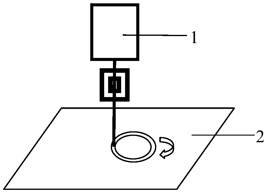
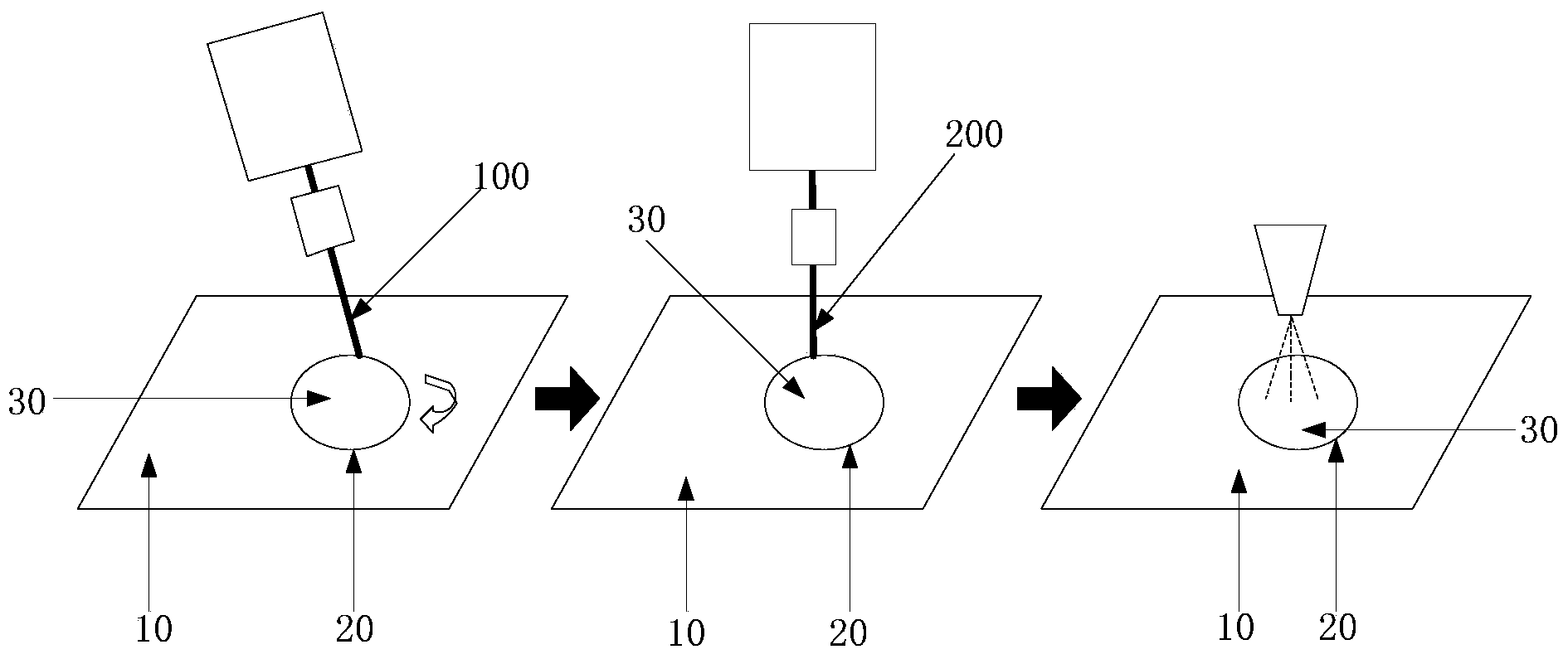
[0041] figure 2 It is a schematic structural diagram of the principle structure of the laser drilling method described in a specific embodiment of the present invention, combined with figure 2 , the laser drilling method described in a specific embodiment of the present invention, comprising:

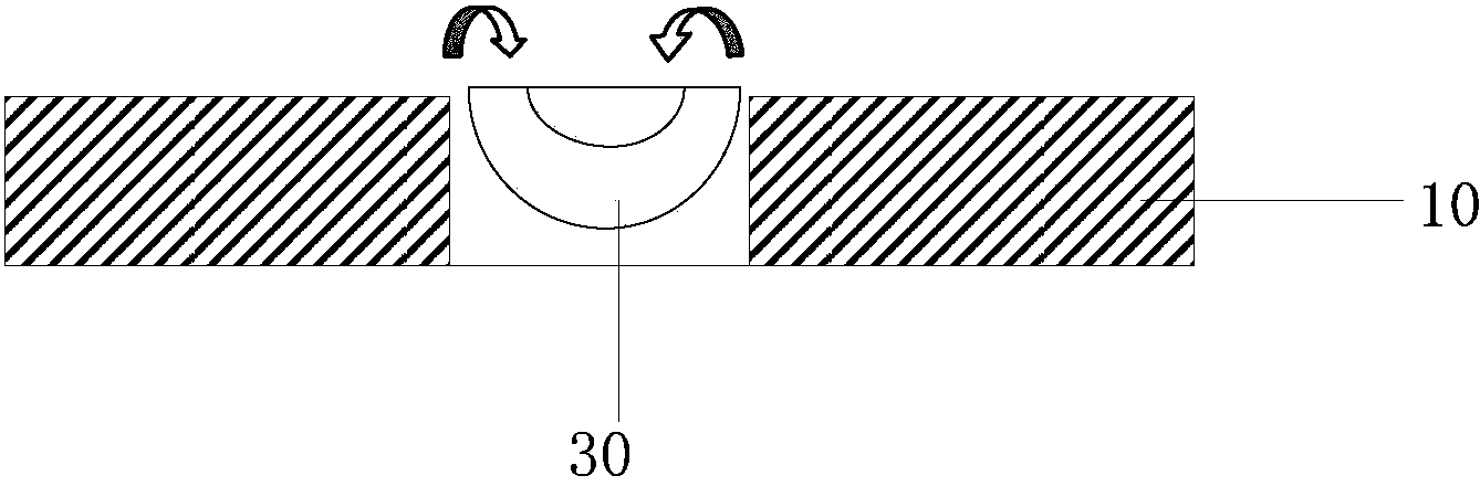
[0042] Step 1, hole boundary forming step: output pulsed laser beam 100, scan on the substrate 10 to be punched, and form the boundary cutting groove 20 of the preformed hole;

[0043] Step 2, material heating step in the hole: output CO 2 laser beam 200, making the CO 2 The laser beam 200 is aligned with the pre-formed hole, and the substrate material 30 of the pre-formed hole is heated for a predetermined time;

[0044] Step 3, hole forming step: ...


PUM


Abstract

The invention provides a laser drilling method and a laser drilling system. The laser drilling method comprises the steps of forming a hole boundary, wherein a pulse laser beam is emitted, scanning is conducted on a substrate where a hole needs to be drilled, and a boundary cutting groove of a preformed hole is formed; heating materials in the hole, wherein a CO2 laser beam is emitted, the CO2 laser beam and the preformed hole are aligned, and substrate materials of the preformed hole are heated for a preset period of time; forming a hole, wherein the substrate materials of the preformed hole are cooled, so that the substrate materials deform and then disengage from the substrate where the hole needs to be drilled. According to the laser drilling method and the laser drilling system, the problems that an existing laser drilling method is not suitable for substrates ultrahigh in chemical strength and the quality of the machined surface of the hole is poor are solved.

Description


Claims


Application Information

Patent Timeline
Owner HEFEI XINSHENG OPTOELECTRONICS TECH CO LTD
Why Eureka
Try Eureka